
We’ve compiled answers to the most frequently asked customer questions, with diagrams to explain the details.
INDEX
QUESTION 1: Bridge setup & topology for wireless bridge
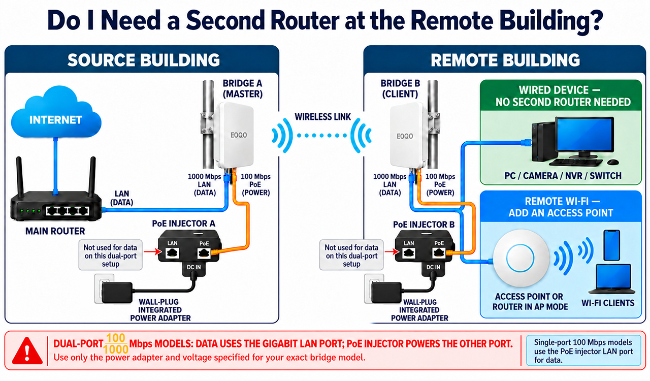
Do I need to buy a second router to use the bridge at the remote building?
ANSWER:
- A bridge carries an Ethernet network between buildings; it does not create Internet service by itself.
- At the source building, connect the router LAN port to the injector LAN port, then connect the injector POE port to the bridge. Use the included power supply specified for that exact model.
- At the remote end, power the second bridge with its matching injector and connect its LAN output to the device you want online. A computer, camera/NVR, switch, or Wi-Fi access point may work, depending on the topology.
- Add a second router only if you need routing or Wi-Fi coverage there; a simple access point may be enough. Confirm compatibility and avoid connecting a remote router’s WAN port unless the chosen topology requires it.
- Test the two bridges side-by-side before mounting them outdoors.
Please refer to the connection diagram below:
QUESTION 2: IP addressing / recovery
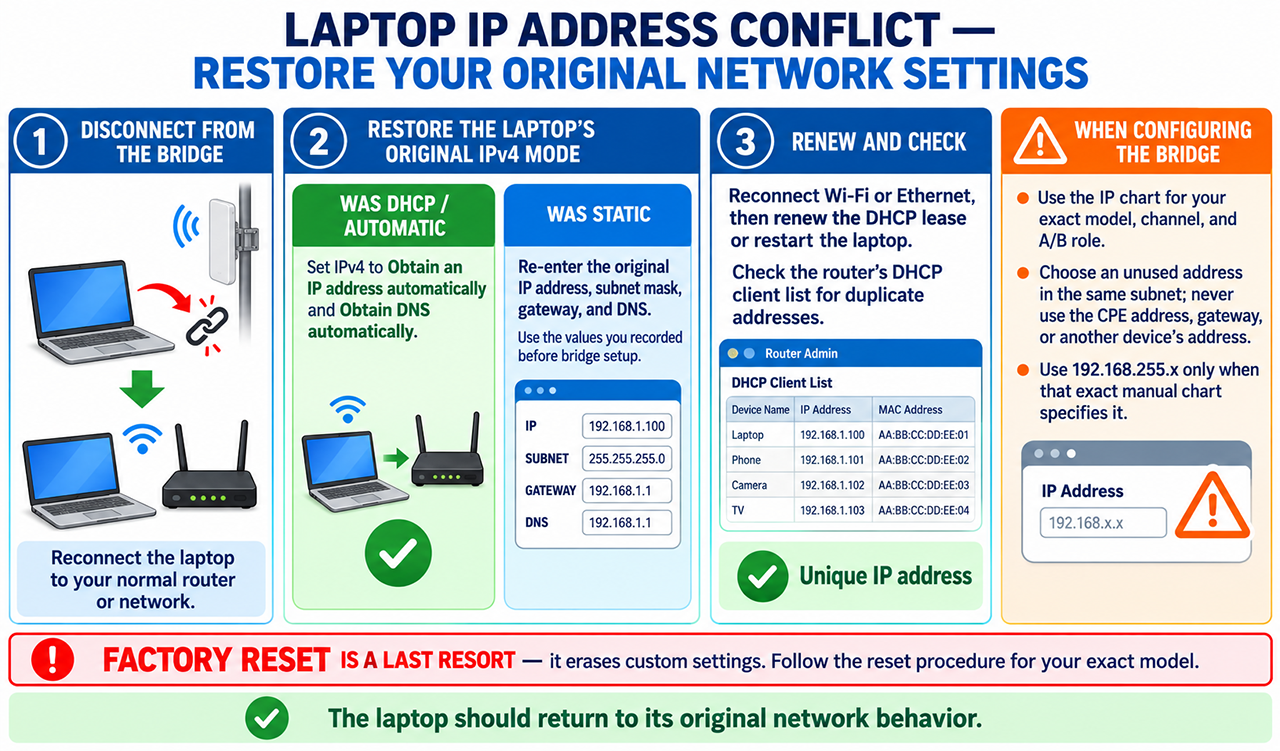
After setup, my laptop says the IP address is already in use. How do I restore its original network settings?
ANSWER:
- Disconnect the laptop from the bridge and reconnect it to the normal router/network. Return the laptop adapter to DHCP if that was its original setting.
- For bridge setup, the uploaded manuals use a model/channel/A-B IP chart. Set the laptop to an unused 192.168.255.x address in the same subnet as the CPE; never choose the CPE address or another device’s IP.
- Check the router DHCP client list for conflicts, then reconnect the laptop to the original network and restore DHCP/static settings as appropriate.
- Reset the bridge only by its exact model procedure; the uploaded series manuals list a 10-second RST hold, but confirm your model first because reset erases custom settings.
- Record the model, channel, A/B role, laptop IP, subnet, and gateway before changing more settings.
Please refer to the connection diagram below:
QUESTION 3: Power / injector fault for Gigabit bridge
One PoE injector started blinking after installation, although both bridges worked during a short test. Is the bridge defective?
ANSWER:
Not necessarily. A blinking light by itself does not confirm that the bridge is defective. First, identify exactly which indicator is blinking: the PoE injector’s power light, the bridge’s PWR/LAN/signal light, or the bridge's digital display. Indicator meanings vary by model.
- Check the model and port labels, and use the included power adapters and PoE injectors. All our current wireless bridge models support both 24V and 48V PoE injectors. For older models, follow the voltage requirements specified on the device label and in the corresponding manual.
- Power everything off and check the connections. Reseat the cables and confirm that the injector’s PoE port connects to the bridge’s designated PoE port. For testing, use short, known-good Cat5e-or-better cables.
- Test one component at a time. Test each bridge close to the other, then swap in a known-good injector only if it has the same voltage and rating. Change one cable or component at a time so you can see whether the blinking follows the injector, cable, or bridge.
- Record the indicators. Note the bridge model, injector rating, which light is blinking, and the CPE’s PWR, LAN, signal, and digital-display states. A blinking CPE display may indicate setup or connection activity on some models; check the LED chart for your exact model before treating it as a fault.
- Contact support if the fault follows a component. If the injector still blinks with the correct adapter and a known-good cable, or the bridge loses power when tested with a known-good, correctly rated injector, send support a short video, photos of the labels and ports, and the test results. UeeVii lists technical support through its contact page.
A brief successful test does not rule out an intermittent cable, power, or connection problem. Factory-reset the bridge only if the model-specific instructions call for it, since a reset can erase custom settings.
QUESTION 4: Power / replacement adapter for CPE220
My CPE220 PoE injector is bad. What other power adapter can I use?
ANSWER:
- All current models support both 24V and 48V PoE injectors. Use the included injector or an approved replacement that meets your model’s voltage, current, polarity and pinout requirements.
- For older models, follow the device label and corresponding manual. Connect a 48V PoE switch only if the exact CPE’s LAN2 port is clearly marked “48V.” According to the manual, an unmarked port supports only the specified 24V PoE injector.
- Connect the CPE’s designated PoE input port to the injector’s POE port, and connect the router or network device to the injector’s LAN port.
- The manual’s DC-power section and specification table list different current requirements. Use the DC input only when your exact unit’s label confirms the required voltage, polarity and current rating. If these details are unclear, use the included matching PoE injector.
QUESTION 5: Link lost / troubleshooting for CPE1200 series
The master shows a signal, but the slave stopped receiving after months of working. What should I check?
ANSWER:
- Check power, cables and port connections. Confirm that both bridges are powered on. Connect each injector’s POE port to the bridge’s designated PoE input port. Reseat all Ethernet connectors and test with short, known-good Cat5e or better cables. All current EOQO wireless bridge models support both 24V and 48V PoE injectors; for older models, follow the voltage and port requirements on the device label and in its manual.
- Confirm the roles and pairing channel. Set the master to A and the slave to B. The units may already be pre-paired. If the indicators show that the wireless link is disconnected, follow your model’s instructions to select the same pairing channel on both units, then wait 2–5 minutes. For models using this indicator pattern, a steady channel display and an illuminated signal indicator indicate successful pairing.
- Check the model-specific indicators. Record the PWR, LAN, signal and channel-display states on both units. A blinking channel display may indicate configuration or connection activity; it does not necessarily mean a hardware failure. Refer to your model’s indicator chart.
- Inspect the outdoor installation. Check for shifted antennas, new obstructions, damaged cables, moisture in connectors or signs of electrical damage. Maintain a clear line of sight and adjust the bridges so they face each other. Monitor the slave’s signal indicators while fine-tuning alignment.
- Distinguish a wireless-link issue from a network issue. Connect a laptop at the slave end through the injector’s LAN port or another designated data port, as specified for your model. If there is no wireless link, focus on power, cabling, pairing, alignment and interference. If the link is established but the laptop cannot access the internet, check the Ethernet connections, laptop network settings and main router’s internet connection.
- Test one component at a time. Use a known-good cable and a compatible, correctly rated injector to test each bridge. Swap injectors only if their voltage, polarity, pinout and power ratings are suitable for both units. If the fault follows a cable or injector, that component is the likely cause. If it consistently follows one bridge despite known-good power and cabling, the bridge may require service or replacement.
If the problem persists, contact EOQO support with photographs of both model labels, a short video showing the indicators and the results of your tests. Change channels or perform a factory reset only when the model-specific troubleshooting instructions require it. A factory reset erases saved custom settings.
QUESTION 6: LAN port / blinking indicator for CPE520
The injector blinks with one CPE520 but stays solid with the other. Does that prove the first radio is damaged?
ANSWER:
- Confirm the model and power requirements. The EOQO CPE520 belongs to the 100 Mbps series and has 10/100 Mbps Ethernet ports. The kit includes a 24V PoE injector. Current EOQO models support both 24V and 48V PoE injectors; for older units, use 48V only if the device label and corresponding manual explicitly confirm compatibility.
- Check the connections with the power off. Connect the CPE’s designated PoE input port to the injector’s POE port. Connect the router or computer to the injector’s LAN port. Test with a short, known-good Cat5e or better Ethernet cable.
- Change one component at a time. If you have two CPE520 units, test each with the same known-good cable and compatible injector. Any replacement injector must meet the unit’s voltage, polarity, pinout and power requirements. Note whether the blinking follows the injector, cable or CPE.
- Check the injector and CPE indicators separately. Record the CPE’s power, LAN, signal and channel-display states. For models using the indicator pattern described in the manual, a flashing channel display indicates configuration or connection activity, while a steady channel number and illuminated signal indicator indicate successful pairing. This pattern does not explain the injector’s LED or every indicator on the CPE.
A single-unit pack requires a compatible second bridge to establish a wireless link.
- Identify which component the problem follows. If the symptom follows the injector when tested with another compatible bridge, check the injector and its power supply. If it consistently remains with the same CPE despite a known-good injector and cable, the CPE or its PoE input port may require service. Contact EOQO support with photographs of the device and injector labels, a short video showing the indicators, and your test results.
QUESTION 7: Overvoltage / no power for Gigabit bridge
I connected a 24V bridge to a 52V PoE switch and now the slave has no power light. Can I keep testing it?
ANSWER:
- Disconnect the power source and confirm compatibility. Current EOQO wireless bridges support both 24V and 48V PoE injectors. This does not automatically confirm compatibility with a 52V source or every PoE switch. Check your exact model’s input specifications and LAN1/LAN2 port labels. For older units, use a 48V PoE switch only through a port explicitly marked “48V”; otherwise, use the included 24V injector.
- Do not reconnect an unverified source. An unlit power LED indicates that the bridge is not powering on, but it does not by itself prove permanent damage. Confirm the permitted voltage, PoE standard, polarity and pinout before reconnecting.
- Test with the supplied power equipment. Disconnect all other power sources, then test the bridge with its included or approved PoE injector and a short, known-good Cat5e or better cable.
- Contact EOQO support if the bridge remains unpowered. Stop testing and provide photographs of the model label and ports, the injector specifications, and the PoE switch model and output rating. Request service or replacement guidance.
- Verify PoE output before connecting other devices. Do not assume that a bridge’s second Ethernet port supplies power. Before connecting a camera or downstream PoE device, confirm that the port explicitly supports PoE output and that its voltage, standard and power capacity match the connected equipment.
QUESTION 8: Hotspot / Wi-Fi
Does the bridge broadcast Wi-Fi, and what password should I use?
ANSWER:
- Find the correct Wi-Fi credentials. On supported EOQO models, the Master’s Wi-Fi is enabled by default. Locate the SSID and password in your model’s Wi-Fi table using the channel digit displayed on the bridge. Credentials may vary by model and channel.
- Distinguish Wi-Fi access from management access. The web-management login and Wi-Fi password are separate credentials. Use the Wi-Fi table to connect your device, and change the default Wi-Fi password after setup if your model supports this option.
- Add an access point for remote Wi-Fi coverage. For reliable coverage at the remote location, connect a separate access point—or a router configured in AP mode—to the Slave-side injector’s LAN port or the bridge’s designated data port.
- Confirm your model’s Wi-Fi capabilities. Refer to the manual for your exact EOQO CPE model before relying on its Wi-Fi or hotspot function. If the listed credentials do not work, verify the model, displayed channel and Wi-Fi settings, then contact EOQO support.
QUESTION 9: Speed / product rating
The listing says 1,000 Mbps, the manual says 300 Mbps, and the ports say 100M. Which speed should I expect?
ANSWER:
- EOQO CPE520 Series: This series has two 10/100 Mbps Ethernet ports. Each wired connection is limited to 100 Mbps, and actual data throughput will be lower because of protocol overhead and operating conditions.
- EOQO CPE1200 Series: This series has one 10/100 Mbps port and one 100/1000 Mbps port. Use the Gigabit port for higher throughput. Traffic passing through the 100 Mbps port remains limited by that connection.
- Understand the advertised speed. Figures such as 300 Mbps or 1,000 Mbps may refer to a wireless link rate, Ethernet port speed or another product variant. These are different specifications and do not guarantee equivalent internet throughput. A Gigabit Ethernet port does not mean the wireless bridge will deliver 1 Gbps.
- Check the entire connection path. Verify the ports, PoE injectors, Ethernet cables, router or switch, and connected devices at both ends. The slowest connection limits throughput; a 100 Mbps injector or negotiated Ethernet link can restrict performance even when the bridge has a Gigabit port.
- Test local throughput separately from internet speed. Connect wired computers at both ends and measure data transfer across the bridge. Check the negotiated Ethernet link speeds as well. Internet speed tests also depend on your router, ISP connection and test server, so they may not reflect the bridge’s capacity.
- Match specifications to your exact model. Check the EOQO model number and hardware version against the corresponding manual and product page. If the specifications conflict, contact EOQO support for clarification rather than relying on figures from another variant.
QUESTION 10: Slow speed + injector LAN port for CPE1200 series
My CPE1200 link across about 450 feet gives only 30–50 Mbps, and an injector LAN jack seems damaged. How should I isolate the problem?
ANSWER:
- Confirm your EOQO CPE1200 port configuration. Port layouts vary by hardware version. Some units have one 10/100 Mbps port and one Gigabit port, while dual-Gigabit versions support Gigabit connections on both LAN1 and LAN2. Follow the labels and wiring diagram for your exact unit.
- Check the PoE injector and cables. Power off the equipment and replace the suspect cable with a short, known-good Cat5e or better cable. Start with the supplied matching injector. Current EOQO models support both 24V and 48V PoE injectors; older units must follow their specified power requirements. Connect the injector’s POE port to the CPE’s designated PoE input and its LAN port to the network device, following the model-specific diagram.
If the LAN jack is visibly damaged or cannot maintain a stable connection, stop using it and test with an approved replacement.
- Verify the negotiated Ethernet speed. Use a known-good Gigabit computer or switch to check each data connection. Confirm that any injector in the data path also supports Gigabit Ethernet. Change one component at a time. A connection negotiated at 100 Mbps limits throughput, while a 10 Mbps or unstable connection can reduce performance further.
- Run a nearby test before checking the 450-foot link. Place the bridges a short distance apart and test local wired throughput with computers at both ends, using known-good power equipment and cables. Then reinstall the bridges with clear line of sight and careful alignment. Compare throughput, signal indicators and negotiated Ethernet speeds. Advertised wireless rates are not guaranteed data-transfer speeds.
- Use the correct performance reference. The corresponding manual lists approximately 150–200 Mbps wireless throughput for the single-Gigabit configuration and up to 350 Mbps with supported dual-Gigabit aggregation. These figures apply to specific configurations and test conditions. Two Gigabit ports alone do not guarantee aggregation or 350 Mbps throughput.
- Contact EOQO support if the issue persists. For a damaged injector jack, request a replacement compatible with your exact unit and required Ethernet speed. If performance remains low with known-good equipment, provide photographs of the CPE and injector labels, negotiated port speeds, signal and LED states, and local wired test results.
QUESTION 11: Hotspot / Wi-Fi for CPE1200 series
The bridge link works, but I cannot see the CPE1200 master’s Wi-Fi hotspot. How do I enable it?
ANSWER:
- Confirm the Master settings. The EOQO CPE1200 manual states that the Master’s Wi-Fi is enabled by default. Set the intended unit to A (Master), check the channel digit on its display, and use the manual’s Wi-Fi chart to identify the corresponding SSID and password.
- Search for the network near the Master. Use a phone or computer that supports 5 GHz Wi-Fi. Your device must also support the bridge’s operating Wi-Fi channel; otherwise, the SSID may not appear.
- Check whether the SSID is hidden. Connect a computer to the CPE through the designated Ethernet data connection. Open the web interface using the IP address listed for that unit and channel in the manual. In the wireless settings, disable Hide SSID, then apply the change. Follow the instructions for your exact EOQO model and firmware.
- Use the correct credentials. The web-management password and Wi-Fi password are separate. Use the SSID and Wi-Fi password listed in the manual’s chart to connect to the wireless network.
- Preserve the bridge connection. If you change the Master’s SSID or Wi-Fi password, update the Slave’s corresponding settings as instructed in the manual. Otherwise, the wireless link may disconnect. If you only want to make the network visible, disable Hide SSID without changing the SSID or password.
QUESTION 12: Starlink Ethernet integration for CPE220 + Starlink Gen 2 router
How can I connect a CPE220 bridge to a Starlink router that has no Ethernet port?
ANSWER:
- Check your Starlink router model. If you have a Gen 2 router without a built-in Ethernet port, use the compatible Starlink Ethernet Adapter to provide a wired connection. Install it according to Starlink’s instructions.
- Connect the EOQO Master bridge. Connect the adapter’s RJ45 Ethernet output to the LAN port on the supplied CPE220 LAN1 port. Connect the injector’s POE port to the Master CPE220’s designated LAN2 port, and set the bridge to A (Master). Power the injector using its supplied power adapter.
- Connect the remote Slave bridge. Set the second CPE220 to B (Slave) and power it with its matching injector. Connect the injector’s POE port to the bridge’s LAN2 input. Connect the Bridge’s LAN1 port to a computer, switch or access point. For remote Wi-Fi coverage, use an access point or a router configured in AP mode.
- Keep Starlink routing enabled for a simple extension. Bypass mode is generally unnecessary when the bridges extend your existing Starlink network and the remote Wi-Fi device operates in AP mode. Use bypass mode only when a separate router will manage the network; enabling it disables the Starlink router’s Wi-Fi.
- Test before outdoor installation. Confirm that both bridges are paired and that a wired device at the Slave end can access the internet. The EOQO CPE220 has 10/100 Mbps Ethernet ports, so traffic through these ports is limited to 100 Mbps, with lower actual throughput. Follow your model’s port diagram and use the supplied matching injectors.
QUESTION 13: Speed / 100 Mbps ceiling for CPE820
Why do my speed tests stop near 110 Mbps even though my Internet plan is faster?
ANSWER:
- Use the Gigabit data port at both ends. Connect your router or computer through each EOQO CPE820’s 1,000 Mbps Ethernet port. Follow the model-specific wiring diagram for PoE power. A 10/100 Mbps port cannot deliver 110 Mbps of actual throughput.
- Verify Gigabit Ethernet connections. Check the negotiated link speed on your computer and managed router or switch, where available. Confirm that both bridges’ data ports and any injector carrying data support Gigabit Ethernet. Use known-good Cat5e or better cables. Any connection negotiated at 100 Mbps limits traffic through it to below 100 Mbps.
- Confirm the test passes through the bridge. Use wired computers and disable Wi-Fi and other network connections on the test devices. A genuine 110 Mbps result exceeds the capacity of a 100 Mbps Ethernet link, so verify the test path, displayed units and readings if they conflict with the negotiated speeds.
- Set realistic wireless expectations. The corresponding series manual lists approximately 150–200 Mbps between the Master and Slave for the single-Gigabit point-to-point configuration. This is a reference figure, not a guaranteed speed. Alignment, obstructions, interference and connected equipment can reduce throughput; internet tests also depend on your router and ISP.
- Compare local and internet throughput. Run a local wired transfer test between computers at opposite ends of the bridge. If local throughput is higher, investigate the router, internet connection and test server. If local throughput also remains near 110 Mbps, check Ethernet negotiation, cables, antenna alignment and wireless signal conditions. Contact EOQO support with your model details and test results if the limitation persists.
QUESTION 14: Gigabit speed troubleshooting for CPE1200 series
My CPE1200 is advertised as Gigabit, but I only get about 80–100 Mbps. What settings or cables should I check?
ANSWER:
- Use the Gigabit data port at both ends. Connect your router or computer through each EOQO CPE1200’s 1,000 Mbps Ethernet port. Follow the model-specific wiring diagram for PoE power. A 10/100 Mbps port cannot deliver 110 Mbps of actual throughput.
- Verify Gigabit Ethernet connections. Check the negotiated link speed on your computer and managed router or switch, where available. Confirm that both bridges’ data ports and any injector carrying data support Gigabit Ethernet. Use known-good Cat5e or better cables. Any connection negotiated at 100 Mbps limits traffic through it to below 100 Mbps.
- Confirm the test passes through the bridge. Use wired computers and disable Wi-Fi and other network connections on the test devices. A genuine 110 Mbps result exceeds the capacity of a 100 Mbps Ethernet link, so verify the test path, displayed units and readings if they conflict with the negotiated speeds.
- Set realistic wireless expectations. The corresponding series manual lists approximately 150–200 Mbps between the Master and Slave for the single-Gigabit point-to-point configuration. This is a reference figure, not a guaranteed speed. Alignment, obstructions, interference and connected equipment can reduce throughput; internet tests also depend on your router and ISP.
- Compare local and internet throughput. Run a local wired transfer test between computers at opposite ends of the bridge. If local throughput is higher, investigate the router, internet connection and test server. If local throughput also remains near 110 Mbps, check Ethernet negotiation, cables, antenna alignment and wireless signal conditions. Contact EOQO support with your model details and test results if the limitation persists.
QUESTION 15: Wi-Fi vs wired speed for CPE1200 series + remote router/AP
Wired speed at the remote router is good, but Wi-Fi through it is slow. Is the bridge at fault?
ANSWER:
- Compare wired performance first. Test the same laptop by Ethernet directly from the remote EOQO bridge’s designated data port or injector LAN port, then through the remote router or access point. If both connections are consistently fast, the slowdown is more likely related to local Wi-Fi than the bridge.
- Check the local Wi-Fi connection. Test close to the access point and compare 2.4 GHz and 5 GHz where supported. Check signal strength, channel congestion, the connected device’s capabilities and the access point’s wireless settings.
- Confirm the remote router’s operating mode. If the main router manages the network and assigns IP addresses, configure the remote router in Access Point mode. Follow its instructions for the uplink port and DHCP settings to avoid an unintended second DHCP server or double NAT.
- Improve access-point placement. Position it in an open area, away from metal objects, enclosed cabinets and interference sources. Test nearby first, then check performance at the locations where Wi-Fi coverage is needed.
- Evaluate the EOQO bridge separately. Disconnect the remote access point and repeat a wired test directly through the bridge’s designated data connection. If wired performance is also slow or unstable, check Ethernet cables, negotiated port speeds, bridge alignment and signal indicators. If wired performance remains good, focus on the access point and Wi-Fi client.
QUESTION 16: Speed / model specification for CPE1200
My CPE1200 speed seems limited to 100 Mbps. Can a setting unlock 1,000 Mbps?
ANSWER:
No software setting can turn a 100 Mbps Ethernet port into a Gigabit port. Check the labels and specifications for your exact EOQO CPE1200 hardware version. The standard single-Gigabit configuration has one 10/100 Mbps port and one Gigabit port; designated dual-Gigabit versions support Gigabit connections on both ports.
- Use the correct power and data ports. For the standard single-Gigabit version, follow its wiring diagram: connect the designated 100 Mbps PoE input to the injector’s POE port for power, and use the bridge’s Gigabit port for data. Connect the Master’s Gigabit port to your router or switch, and the Slave’s Gigabit port to the remote computer, switch or access point. Apply this arrangement only if it matches your unit’s port labels.
- Check the entire Ethernet path. Ensure that the data ports on both bridges and all connected equipment support Gigabit Ethernet. Any injector carrying data must also support Gigabit speeds. Use known-good Cat5e or Cat6 cables and verify that the connections negotiate at 1 Gbps.
- Distinguish link speed from throughput. If a connection reports 100 Mbps, check the selected port, cable and connected device. If it reports 1 Gbps but internet speed remains near 100 Mbps, run a local wired transfer test between computers at opposite ends of the bridge. This helps separate bridge performance from ISP and test-server limitations.
- Set realistic wireless expectations. The corresponding series manual lists approximately 150–200 Mbps wireless throughput for the single-Gigabit configuration and up to 350 Mbps with supported dual-Gigabit aggregation. These figures depend on the model, configuration and operating conditions. Gigabit Ethernet ports do not guarantee 1,000 Mbps wireless throughput, and two Gigabit ports do not automatically enable aggregation.
- Investigate persistent slow performance. If both data connections negotiate at 1 Gbps but local throughput remains unexpectedly low, check signal strength, antenna alignment, obstructions, interference and link indicators. Contact EOQO support with your model and hardware version, port-label photographs, negotiated link speeds and test results.
QUESTION 17: End-to-end speed test for CPE1200 series
The source side tests near 950 Mbps, but the remote side gets only about 50 Mbps even during a close-range test. What is the right test sequence?
ANSWER:
- Use the Gigabit data port at both ends. Connect your router or computer through each EOQO CPE1200’s 1,000 Mbps Ethernet port. Follow the model-specific wiring diagram for PoE power. A 10/100 Mbps port cannot deliver 110 Mbps of actual throughput.
- Verify Gigabit Ethernet connections. Check the negotiated link speed on your computer and managed router or switch, where available. Confirm that both bridges’ data ports and any injector carrying data support Gigabit Ethernet. Use known-good Cat5e or better cables. Any connection negotiated at 100 Mbps limits traffic through it to below 100 Mbps.
- Confirm the test passes through the bridge. Use wired computers and disable Wi-Fi and other network connections on the test devices. A genuine 110 Mbps result exceeds the capacity of a 100 Mbps Ethernet link, so verify the test path, displayed units and readings if they conflict with the negotiated speeds.
- Set realistic wireless expectations. The corresponding series manual lists approximately 150–200 Mbps between the Master and Slave for the single-Gigabit point-to-point configuration. This is a reference figure, not a guaranteed speed. Alignment, obstructions, interference and connected equipment can reduce throughput; internet tests also depend on your router and ISP.
- Compare local and internet throughput. Run a local wired transfer test between computers at opposite ends of the bridge. If local throughput is higher, investigate the router, internet connection and test server. If local throughput also remains near 110 Mbps, check Ethernet negotiation, cables, antenna alignment and wireless signal conditions. Contact EOQO support with your model details and test results if the limitation persists.
QUESTION 18: Camera / NVR topology for CPE220
Can I connect two cameras directly through the bridge to an NVR without adding a separate network box?
ANSWER:
An EOQO CPE220 wireless bridge can transmit video and network traffic between IP cameras and an NVR. To connect two cameras at the same remote location, use a suitable network switch and provide compatible power for each camera.
- Connect both cameras through a switch. Connect the remote bridge’s LAN output to a network switch, then connect both cameras to that switch. At the main location, connect the Master bridge’s LAN output to the network containing your NVR. If you plan to use the NVR’s built-in camera ports, check its manual to confirm that the proposed connection is supported.
- Provide compatible camera power. Use a PoE switch that matches the cameras’ PoE requirements, or power each camera with its approved adapter or injector. The EOQO bridge’s included PoE injector powers the bridge; it should not be assumed compatible with your cameras.
- Follow the CPE220 wiring diagram. Connect each bridge’s designated PoE input to its injector’s POE port. Connect the network equipment to the injector’s LAN port. Before connecting any camera to a PoE output, confirm that the voltage, PoE standard, and power capacity match the camera’s requirements.
- Check IP addresses and NVR access. Ensure that both cameras have unique IP addresses and are reachable from the NVR. Some NVRs place their built-in PoE camera ports on a separate, isolated network. Follow the NVR’s instructions when adding cameras connected through the wireless bridge.
- Test one camera, then add the second. Confirm that each camera appears on the NVR and that both streams remain stable during live viewing and recording. The EOQO CPE220 uses 100 Mbps Ethernet connections, while usable wireless throughput may be lower. Allow capacity for both cameras’ combined bitrate and other network traffic.
If either camera disconnects or video becomes unstable, contact EOQO support with your bridge, camera, and NVR model numbers, a connection diagram, and the configured video bitrates.
QUESTION 19: PoE voltage compatibility for CPE220 | CPE355 | CPE520 | CPE820 + 48V switch
Can I power my 24V CPE220 from a 48V PoE switch, or is one PoE injector port enough?
ANSWER:
All current EOQO wireless bridges include a 24V PoE injector and also support compatible 48V PoE power sources. Older EOQO models do not support 48V PoE and must use their specified 24V power supply. Check your exact model and hardware version before connecting a different power source.
- Use the included 24V PoE injector for straightforward setup. Connect its POE port to the bridge’s designated PoE input and its LAN port to your router, switch, or other network device.
- Use 48V PoE only with a compatible current model. Confirm that the PoE switch or injector matches the bridge’s supported PoE type and wiring requirements. Voltage alone does not establish compatibility.
- One injector powers one bridge. The injector’s LAN port carries network data; it does not supply PoE power. A two-bridge kit normally requires one power source at each end.
- Keep older models on 24V. Do not connect a 48V PoE source to an older EOQO bridge. Use the original injector or an approved replacement with the correct voltage, polarity, and sufficient current capacity.
If you are unsure whether your bridge is a current or older version, contact EOQO support with photos of its model label and port markings before connecting a 48V power source.
QUESTION 20: Link but no Internet for CPE355 | CPE520
Both bridge units show green lights, but the remote building has no Internet. What should I test?
ANSWER:
Green signal lights on your EOQO wireless bridges indicate an established wireless link. They do not confirm Internet access or a working Ethernet connection at the remote location. Follow these steps to identify where the connection is failing:
- Verify Internet access at the source. Connect a computer directly to the main router and confirm that you can browse the Internet. Then check that the Master bridge’s data connection leads to a LAN port on that router.
- Check the wiring for your exact EOQO model.
- 100 Mbps series: Connect the bridge’s designated PoE input to the injector’s POE port and the router or remote network device to the injector’s LAN port.
- Single-Gigabit versions with separate power and data ports: Connect the designated 100 Mbps PoE input to the injector’s POE port for power. Use the bridge’s Gigabit port for data—toward the router at the Master end and the remote device at the Slave end.
Follow your model’s port labels and wiring diagram, as hardware versions may differ.
- Test with a laptop at the remote end. Disconnect the remote router or access point and connect a laptop directly to the bridge’s data output specified above. Turn off the laptop’s Wi-Fi and configure Ethernet to obtain an IP address and DNS settings automatically.
- Check the laptop’s network settings. It should receive an IP address in the main router’s LAN subnet, along with the correct default gateway and DNS server. If it receives no address or a self-assigned 169.254.x.x address, check the Ethernet cable, port connections, router DHCP service, VLAN configuration, and any relevant network-isolation settings.
- Test connectivity, then reconnect your equipment. Check access to the main router’s gateway, then a public IP address, and finally a website by name. A failed ping alone is not conclusive, as some devices block ping requests. If the laptop has Internet access, reconnect the remote router in Access Point mode when the main router should handle DHCP. If direct access still fails, try a short, known-good Ethernet cable and recheck the model-specific wiring.
If the problem continues, contact EOQO support with your bridge model, a connection diagram, photos of both units’ indicators, and the laptop’s IP address, gateway, and DNS details.
QUESTION 21: Alternative DC power for CPE220 | CPE355 | CPE520 | CPE820
Can I run a CPE220 from a battery through its DC jack, and what voltage and polarity does it need?
ANSWER:
All EOQO wireless bridges equipped with a DC power input support a regulated 12V DC, 1A power supply. You may use this input as an alternative to the included 24V PoE injector.
- Use a compatible DC adapter. Choose a regulated 12V DC supply rated for at least 1A. Confirm that the connector size and polarity match the markings on your EOQO bridge.
- Use regulated power for battery or solar installations. Do not connect an unregulated battery or solar panel directly to the DC input. Use a suitable regulator that delivers a stable 12V DC output with at least 1A capacity.
- Choose one power method. Use either the DC input or a compatible PoE source. Do not connect both simultaneously unless EOQO confirms that your exact model supports this arrangement.
- Confirm the connection before powering on. If the connector size or polarity is unclear, send EOQO support a photo of the device label and DC port for guidance.
QUESTION 22: PoE passthrough for CPE355 | CPE520 | CPE820
Can LAN2/PoE passthrough power a second antenna or another device?
ANSWER:
Do not use LAN2 to power a second device unless the manual for your exact CPE355 hardware revision explicitly identifies it as a PoE output and specifies its output voltage, pinout, and power budget. The uploaded 100 Mbps and Gigabit manuals describe PoE-capable CPE ports, but do not establish PoE passthrough output.
- Treat “PoE” as an input unless the manual says “PoE out” or “PoE passthrough.” The CPE355 manual describes its POE/LAN port as receiving 24V power and carrying data; its LAN port is described as data-only.
- Port labels vary by model and revision. UeeVii describes two ports on a comparable bridge as accepting 24V PoE input. AdaLov likewise describes PoE-capable ports on its CPE355 manual, but that wording alone does not confirm power output to another device.
- Power the second antenna or device separately with its own compatible injector or a PoE switch that matches its voltage and PoE standard.
- Do not connect it based only on the “PoE” label. Verify the exact port’s direction and electrical specifications first.
QUESTION 23: Remote Wi-Fi / second router for CPE bridge
Do I need a router at the slave location to get Wi-Fi in the remote building?
ANSWER:
Not always. Whether you need a separate Wi-Fi device at the remote building depends on your EOQO bridge model and operating mode. A wireless bridge extends the network between locations, but the Slave does not necessarily broadcast Wi-Fi by default.
- Check your model’s hotspot support. The EOQO 100 Mbps-series manual describes enabling a Slave Wi-Fi hotspot through the web interface. The Gigabit-series manual documents Wi-Fi enabled by default on the Master, but does not describe the same Slave-hotspot configuration. Follow the instructions for your exact model.
- Use a separate access point for remote Wi-Fi coverage. Connect an access point to the Slave’s designated Ethernet data output. This lets you position the access point inside the building for better coverage while keeping the bridge outdoors and aligned with the Master.
- A separate router is optional. An access point is sufficient when the main router already manages the network. If you use a Wi-Fi router at the remote location, select Access Point mode so the main router continues to assign IP addresses through DHCP, unless you intentionally need a separate routed network.
- Test the wired connection first. Connect a laptop to the Slave-side data output, following your model’s wiring diagram. For models with separate PoE power and Gigabit data ports, use the designated Gigabit port for the laptop or access point. Once wired Internet access works, connect and configure your Wi-Fi device.
For help choosing the correct connection or enabling a supported hotspot, contact EOQO support with your bridge model and hardware version.
QUESTION 24: Starlink + building-to-building router for Bridge + Starlink Gen 3 Standard 4 4X Enterprise Router
Can I put a bridge between Starlink and a router in the next building if the remote router has no Internet?
ANSWER:
Yes. The remote router does not need its own Internet service. An EOQO wireless bridge pair carries the network connection from your Starlink installation to the other building, where a router or access point can provide local Wi-Fi.
- Check your Starlink Ethernet connection. Connect the Master-side network cable to an available Ethernet LAN port on your Starlink router. The Starlink Gen 3, Standard 4, 4X, Enterprise router has two Ethernet LAN ports; other kits may require a compatible Ethernet adapter or a different connection arrangement. Check your exact Starlink hardware.
- Follow your EOQO model’s wiring diagram:
- 100 Mbps series: Connect the bridge’s designated PoE input to the injector’s POE port and the router or remote network device to the injector’s LAN port.
- Single-Gigabit versions with separate power and data ports: Connect the designated 100 Mbps PoE input to the injector’s POE port for power. Use the bridge’s Gigabit port for data—toward the router at the Master end and the remote device at the Slave end.
- Select the remote router’s operating mode. To extend the same network, use Access Point mode, allowing the Starlink router to manage DHCP. Connect the bridge’s remote data output to the port specified in the remote router’s AP-mode instructions. To create a separate routed network, connect to the remote router’s WAN port and select automatic IP addressing (DHCP) for its WAN connection. This arrangement may introduce double NAT.
- Test the bridge before connecting the remote router. First confirm that Starlink has Internet access. Then connect a laptop directly to the Slave-side data output, disable its Wi-Fi, and set Ethernet to obtain an IP address automatically. If the laptop can access the Internet, the bridge is carrying the connection successfully.
- Reconnect the remote router and verify its settings. If it still reports no Internet, check its operating mode, selected uplink port, Ethernet cable, and WAN DHCP settings where applicable. In AP mode, ensure that the remote router is not running a competing DHCP server.
If you need assistance, contact EOQO support with your Starlink hardware model, EOQO bridge model, remote router model, and a diagram or photos of the connections.
QUESTION 25: Starlink Mini Connection for building-to-building router for Bridge + Starlink Gen 3 Standard 4 4X Enterprise Router
How I can connect the bridge to my starlink Mini router?
ANSWER:
- Check your Starlink Ethernet connection. Connect the Master-side network cable to an available Ethernet LAN port on your Starlink router. The Starlink Mini router has two Ethernet LAN ports; other kits may require a compatible Ethernet adapter or a different connection arrangement. Check your exact Starlink hardware.
- Follow your EOQO model’s wiring diagram:
- 100 Mbps series: Connect the bridge’s designated PoE input to the injector’s POE port and the router or remote network device to the injector’s LAN port.
- Single-Gigabit versions with separate power and data ports: Connect the designated 100 Mbps PoE input to the injector’s POE port for power. Use the bridge’s Gigabit port for data—toward the router at the Master end and the remote device at the Slave end.
- Select the remote router’s operating mode. To extend the same network, use Access Point mode, allowing the Starlink router to manage DHCP. Connect the bridge’s remote data output to the port specified in the remote router’s AP-mode instructions. To create a separate routed network, connect to the remote router’s WAN port and select automatic IP addressing (DHCP) for its WAN connection. This arrangement may introduce double NAT.
- Test the bridge before connecting the remote router. First confirm that Starlink has Internet access. Then connect a laptop directly to the Slave-side data output, disable its Wi-Fi, and set Ethernet to obtain an IP address automatically. If the laptop can access the Internet, the bridge is carrying the connection successfully.
- Reconnect the remote router and verify its settings. If it still reports no Internet, check its operating mode, selected uplink port, Ethernet cable, and WAN DHCP settings where applicable. In AP mode, ensure that the remote router is not running a competing DHCP server.
If you need assistance, contact EOQO support with your Starlink hardware model, EOQO bridge model, remote router model, and a diagram or photos of the connections.
QUESTION 26: Firmware / software update
Is there newer firmware than version 1.63 for my bridge, and should I update it before using point-to-multipoint?
ANSWER:
No. all of EOQO wireless bridges are can not update the firmware, we had installed the last version firmware when we assemble the product.
QUESTION 27: Point-to-multipoint / camera topology for CPE520
Can I add one bridge so two cameras at separate locations can transmit to one receiver?
ANSWER:
Yes, provided your exact EOQO wireless bridge model supports point-to-multipoint (PtMP) operation. Install one Master (A) at the NVR or receiving network and one Slave (B) at each remote camera location. A compatible third bridge can extend an existing pair to serve two remote locations.
- Confirm compatibility before adding a unit. The referenced EOQO manuals illustrate one Master connected to three Slaves. Verify that your model and firmware support PtMP and the number of Slaves required. An additional radio must be compatible with your existing bridges.
- Configure the roles and pairing. Set the receiving-side bridge to A/Master and both camera-side bridges to B/Slave. Follow your model’s pairing instructions, including selecting the same channel where required. Confirm that both Slaves establish stable connections with the Master.
- Connect the cameras and provide suitable power. Power each bridge with its supplied PoE injector. For the 100 Mbps series, connect the bridge’s designated PoE input to the injector’s POE port and the camera or local switch to its LAN port. For models with separate power and Gigabit data ports, use the designated Gigabit port for data. Power cameras separately using compatible adapters or a suitable PoE switch. Connect the Master’s data output to the network containing the NVR.
- Check positioning and available bandwidth. Both Slaves must have clear line of sight to the Master and remain within its antenna coverage angle. The Slaves share the Master’s wireless capacity, so allow sufficient bandwidth for both cameras’ combined video bitrates and other traffic. Models with 10/100 Mbps Ethernet ports deliver usable wired throughput below 100 Mbps.
- Test before mounting outdoors. Set up all three bridges together and confirm that both camera streams reach the NVR and remain stable during recording. Check that the cameras have unique IP addresses and are accessible from the NVR, then verify performance at the intended installation locations.
Contact EOQO support with your existing bridge model and hardware version for help choosing a compatible additional unit.
QUESTION 28: Settings / pairing display for CPE Bridge
Why do my SSID/security settings appear to disappear, and what do the flashing “H” and channel number mean?
ANSWER:
- Understand your EOQO bridge’s display indicators. In the referenced 100 Mbps and Gigabit-series manuals, a flashing “H” indicates manual configuration status. A flashing channel number can indicate configuration or connection activity. A steady channel number with the signal indicator illuminated indicates successful pairing. Flashing alone does not mean your SSID or password has been erased.
- Disable Auto Mode before saving custom wireless settings. For the EOQO 100 Mbps models covered by the manual, DIP Switch Control (Auto Mode) can restore automatically generated wireless settings after a restart or power cycle. To retain a custom SSID and password, disable this option in the web interface and click OK. Then update your settings and click Apply.
With Auto Mode disabled, use the web interface to configure pairing; the physical A/B and reset controls no longer perform their automatic configuration functions as described in the manual.
- Keep the Master and Slave settings matched. If you change the Master’s bridge SSID or wireless password, update the corresponding settings on the Slave to restore the link. For the documented 100 Mbps configuration, keep the Master’s SSID visible so the Slave can detect it. A temporary disconnection during these changes does not necessarily mean the settings were lost.
- Save changes on the intended unit. Confirm whether you are logged into the Master or Slave, click Apply, and wait for the process to finish before restarting or disconnecting power. Reconnect using that unit’s current management IP address. Avoid a factory reset unless you are ready to restore its wireless, pairing, and network settings.
- Follow your exact model’s instructions. The Auto Mode behavior described above applies to the referenced EOQO 100 Mbps models and should not be assumed to apply to every Gigabit version. If settings continue to revert, contact EOQO support with your model label, hardware and firmware versions, relevant screenshots, and a short video of the display indicators. Hide passwords before sharing screenshots.
QUESTION 29: PoE injector blinking / no power
One bridge fails to power up and its PoE adapter slowly blinks, even with a short cable. Is the adapter or bridge bad?
ANSWER:
- Verify the exact power requirements. Use the injector specified for your exact model and check its voltage, polarity, and rating. Use 48V only if the bridge port is explicitly marked as 48V compatible; bridge models differ in their PoE requirements.
- Power off and check the connections. Connect the bridge’s designated PoE port to the injector’s PoE port. For testing, use a short, known-good Cat5e-or-better cable.
- Swap one component at a time. Try a known-good, correctly rated injector with the suspect bridge. You can test the suspect injector with the working bridge only if their voltage, polarity, and rating match. Do not substitute an injector just because its plug fits.
- Watch which symptom follows which part. Check whether the CPE’s power LED turns on. If the blinking follows the injector, suspect the injector or its power supply; if the same CPE still will not power up with a confirmed matching injector and cable, suspect the CPE or its PoE port.
- If it still fails, stop testing and contact support. Send the model label, injector rating, port labels, and a short video showing the blinking pattern and CPE indicators. UeeVii provides model-specific manuals and support, so use the guide for the exact unit.
QUESTION 30: Transmit power
What is the maximum selectable transmit power on the CPE220?
ANSWER:
EOQO CPE220 maximum transmit range is 2KM, we suggest use for 0.5KM for best performance. Long range will reduce the data transmit power and slow the speed, some time may the connection is not stable.
QUESTION 31: Web interface login
I can find the bridge IP address but the login page asks for a password. Is that the Wi-Fi password?
ANSWER:
No. Your EOQO bridge’s web-management password and Wi-Fi password serve different purposes. The referenced CPE-series manuals list admin as both the default web username and password. If the login page asks only for a password, enter admin, provided the default credentials have not been changed.
- Connect through the correct data port. For models managed through the PoE injector, connect your computer to the injector’s LAN port. For models with separate power and Gigabit data ports, follow the model’s wiring diagram. Set the computer’s Ethernet IP address to the same subnet as the bridge, using a different address from the bridge itself.
- Open the correct management IP address. Check the IP chart for your exact EOQO model and select the address matching its displayed channel and A/Master or B/Slave role. If the management IP was changed, use the updated address.
- Use the web-management credentials. If admin does not work, the login password may have been changed. The Wi-Fi password will not work unless someone deliberately configured both passwords to match.
- Reset only when necessary. A factory reset can erase customized network, wireless, and pairing settings. Follow the reset procedure for your exact model and hardware revision, and be ready to configure the bridge again.
- Update and record your passwords. After logging in, change the default web-management credentials where supported. Store them securely and separately from your Wi-Fi credentials.
If you still cannot log in, contact EOQO support with your model label, displayed channel, A/B role, and a screenshot of the login page. Do not include passwords.
QUESTION 32: Camera count / bandwidth limit
How many IP cameras can I connect through a CPE355 and a network switch?
ANSWER:
There is no fixed camera count. It depends on the cameras’ combined bitrate and the bridge’s real-world capacity.
- Estimate the total camera traffic. Add each camera’s peak bitrate, including high-resolution recording, night/IR operation, and motion-related bitrate increases. Leave capacity for network overhead and other traffic.
- Keep within the bridge’s limits. The CPE355 listing specifies 10/100 Mbps Ethernet and up to 100 Mbps network speed. Actual usable throughput may be lower, so test the link under the intended conditions.
- Use the switch for port expansion. If the cameras are at one remote location, connect them to a switch and connect that switch to the remote bridge’s network handoff. Use a PoE switch if it must power PoE cameras; otherwise, power the cameras separately. Do not assume the bridge injector powers them.
- For cameras at separate locations, each location needs a compatible Slave bridge in a supported PtMP setup, within the Master’s coverage. Confirm the supported Slave count for the exact hardware and firmware before adding radios. UeeVii describes PtMP for its bridge range, but that does not establish compatibility or a camera limit for every model.
- Test all cameras streaming at once and check for dropped frames, latency, and recording interruptions before relying on the installation.
QUESTION 33: Web interface access / AP setup
I want to use the bridge pair to provide outdoor Wi-Fi, but I cannot log in to the bridge IP. How do I set it up?
ANSWER:
First the Wi‑Fi enabled by default on the Master. connect the bridge pair and verify the link. For management access, your computer must be on the same subnet as the bridge. The web login is separate from the Wi‑Fi password.
- Connect the computer by Ethernet to the PoE injector’s LAN port. Confirm the injector’s PoE port is connected to the bridge. Temporarily turn off the computer’s Wi‑Fi and VPN.
- Set the computer’s Ethernet IPv4 address to an unused address such as 192.168.255.2, with subnet mask 255.255.255.0. Do not use the bridge’s own address.
- Read the bridge’s channel display and A/B role, then use the matching IP in that model’s chart. For example, on one UeeVii model, channel 1 maps to 192.168.255.101 for A/Master and 192.168.255.201 for B/Slave. The chart can vary by model.
- Enter that IP in a browser. The uploaded manuals list admin as the default username and password; Default are admin/admin. If the password was changed, use the current one. Avoid resetting unless you’re ready to restore the bridge configuration.
- For outdoor Wi‑Fi coverage at the remote location, connect an outdoor access point to the Slave-side injector’s LAN connection. Configure it in AP mode and follow its instructions for DHCP.
After setup, return the computer’s Ethernet setting to DHCP/automatic.
QUESTION 34: Access point mode
Can I use a CPE355 itself as an access point, or do I need a separate AP?
ANSWER:
The CPE355 can broadcast a preconfigured Wi‑Fi hotspot in its auto-pairing mode.
- If you want reliable Wi‑Fi for phones, laptops, or other devices at the remote building, connect a separate router or access point to the Slave-side PoE injector’s LAN port.
- Set that router to AP mode and leave DHCP on the main router, unless you intentionally want a separate routed network.
- First connect a laptop by Ethernet to the Slave-side injector’s LAN port and confirm that the bridge is delivering network access. Then connect and configure the AP.
- If you want to use the CPE355’s own hotspot, check its channel-specific SSID and password in the CPE355 manual and test coverage near the bridge A.
- A separate AP is the predictable choice for extending usable Wi‑Fi coverage throughout the remote building.
QUESTION 35: Management IP / same LAN
Can I change the bridge management IPs to fit my office subnet, such as 192.168.100.x, and keep the warehouse on the same network?
ANSWER:
No, you can not change the bridge IPs, if change it you may lost the connection, need repair again.
QUESTION 36: Starlink point-to-point Connection
In the Starlink point-to-point diagram, do the master and slave look reversed? Which unit connects to the main router?
ANSWER:
- For the usual setup that extends Starlink Internet to another building, place A/Master at the Starlink router (Internet source) and B/Slave at the remote building.
- At the source, connect the Starlink router’s Ethernet output to the A/Master Bridge’s LAN side, then connect the injector’s PoE side to the Master CPE’s designated PoE port. Follow the wiring diagram for your exact model; some Gigabit versions use a separate port for network data.
- At the remote end, connect the injector’s PoE side to the Slave CPE’s designated PoE port and connect the B/Slave Bridge’s LAN side to the remote computer, switch, or access point.
- The bridge carries the Ethernet network between buildings. It does not replace the Starlink router or provide Internet service by itself.
QUESTION 37: Reset / one unit keeps blinking
The bridge used to work, but one unit now blinks continuously and will not reset. What should I try?
ANSWER:
A flashing display does not automatically mean the bridge has failed. In the uploaded manuals, a flashing digit can indicate configuration or connection activity; a steady channel number indicates successful pairing.
- Check power and cabling. Power the unit off, confirm you are using its matching PoE injector, and test with a short, known-good Ethernet cable.
- Test the radios separately. If the injector ratings match, try the suspect unit with the other working injector. Change one component at a time and note whether the symptom follows the injector, cable, or radio.
- Check the pairing settings. Confirm the A/B roles are correct and the channel matches the other bridge. Test the pair close together before reinstalling them.
- Use only the reset procedure for the exact model. The two uploaded manuals specify holding RST for 10 seconds. On the uploaded 100 Mbps series, the manual says the physical RST control is disabled when DIP Switch Control is off; check the model’s instructions if the button appears inactive. Resetting may erase custom settings.
- If it still blinks and will not reset, stop repeated reset attempts. Send support the model label, injector rating, and a short video showing the display and LEDs; request model-specific service or replacement guidance.