Security policy
(edit with the Customer Reassurance module)
 Delivery policy
(edit with the Customer Reassurance module)
 Return policy
(edit with the Customer Reassurance module)
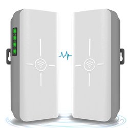
CPE520 wireless bridge kits is one pair of outdoor high power and high performance 300Mbps wireless bridges, which works at 5GHz frequency. Supports Point-to-Point and Point-to-Multipoint wireless connection. It is more stable and higher speed and anti-interference performance than 2.4GHz wireless bridge. Moreover, it is easy to manage through the WEB interface.
CPE520 Kits Function:
CPE520 Kits Application:
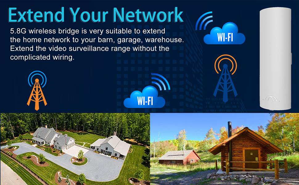
The CPE335 kits is great to extend your home internet network to another building without wire connection, you can share your network to your barn garage, warehouse, workshop or small store near to your home, it also works for enterprise to share the internet from different office, workshop, warehouse and etc.
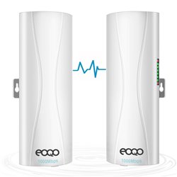
We offer a pair of wireless bridge in the package, we need to set one works as master mode, and another works as slave mode.
Wireless Bridge Master & Slave Set:
1.Master Bridge Set
Move the mode switch to "A" position, the device works as master mode
2.Slave Bridge Set
Move the mode switch to "B" position, the device works as slave mode
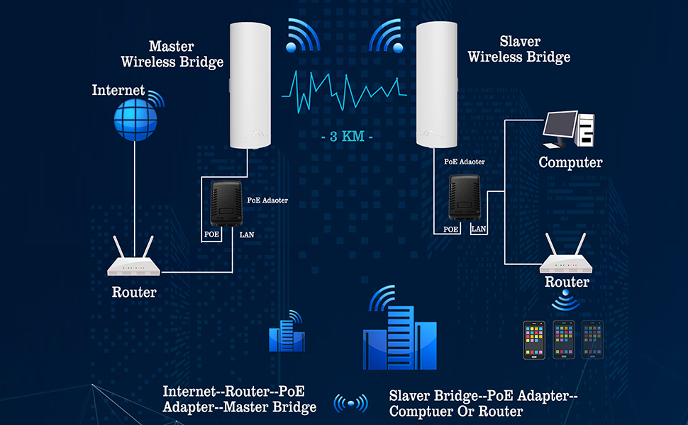
1.Bridge A Connection - Master Bridge
Step 1: the LAN port of the PoE Adapter connect to the router through an ethernet cable.
Step 2: the PoE port of the PoE adapter connect to LAN port of the master wireless bridge by another ethernet cable.
2.Bridge B Connection - Slave Bridge
Step 1: the PoE port of the PoE adapter connect to the LAN port of slave bridge through an ethernet cable
Step 2: the LAN port of the PoE adapter connect to the LAN port of the computer or router by another ethernet cable
The master bridge transfer data to slave bridge works as point to point mode to extend network access to another house, office, building for internet surfing. The master bridge also output WiFi hot point, such as outdoor access point, you can open the WiFi connection setting on your cellphone, or laptop, you will find the WiFI name CPE5G_5Gxxx, enter the password to get access.
The access password is pre-programmed, it is different depend on what channel the wireless bridge working, but only change the last two or three numbers.
For example: the WiFi hot point name is CPE5G_5G161, and the default password is zllinkcpe123456161, if the name is CPE5G_5G153, the password will be zllinkcpe123456153, the last three numbers of the password is match to the last three numbers of the name, zllinkcpe123456 is the same, you can find the password with a little bit change for different channel.
Wireless Bridge Master & Slave Set:
1.Master Bridge Set
Move the mode switch to "A" position, the device works as master mode
2.Slave Bridge Set
Move the mode switch to "B" position, the device works as slave mode
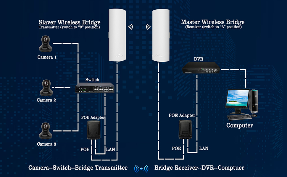
Wireless Bridge Connection
1.Bridge A Connection - Master Bridge
Step 1: the LAN port of the PoE Adapter connect to the DVR through an ethernet cable.
Step 2: the PoE port of the PoE adapter connect to LAN port of the master wireless bridge by another ethernet cable.
2.Bridge B Connection - Slave Bridge
Step 1: the PoE port of the PoE adapter connect to the LAN port of slave bridge through an ethernet cable
Step 2: the LAN port of the PoE adapter connect to the LAN port of the switch by another ethernet cable
Point to Point video surveillance, expand your video surveillance range, easily management all your surveillance camera in one DVR system without complicated wiring. Transfer your video surveillance network IP cameras data from another building to your DVR, easy to management all the cameras in one system.
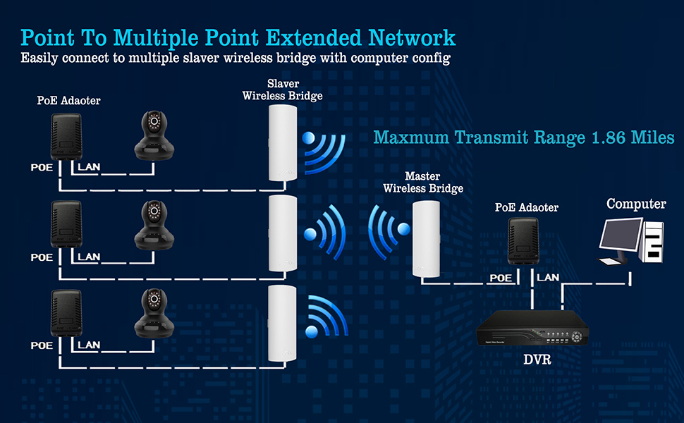
Wireless Bridge Connection
1.Bridge A Connection - Master Bridge
Step 1: the LAN port of the PoE Adapter connect to the DVR through an ethernet cable.
Step 2: the PoE port of the PoE adapter connect to LAN port of the master wireless bridge by another ethernet cable.
2.Bridge B Connection - Slave Bridge
Step 1: the PoE port of the PoE adapter connect to the LAN port of slave bridge through an ethernet cable
Step 2: the LAN port of the PoE adapter connect to the LAN port of the IP cameras by another ethernet cable
Install the slave bridges face to face to the master bridge, and the direction angle no more than 60 degrees, this connection need login into computer to configure the IP address for different slave, please read the user manual for details.
In this way, you can easy transfer the network camera video streaming from different buildings to the DVR of the control center, point to multiple point function is great for you to monitoring multiple buildings without complicated wiring.
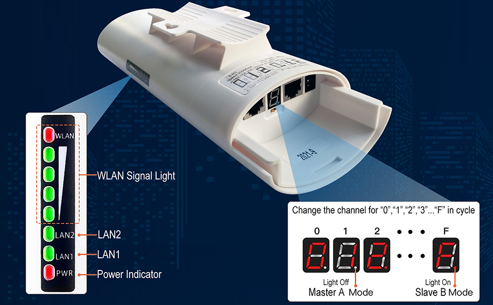
The wireless bridges work by two modes, auto pairing mode with pre-programed suit for newbie, customize mode suit for experienced user.
Auto pairing mode:
connect it to the PoE power adapter, the Power LED turns green on, system is power on, when the both bridges all are power on, it will auto pair in few minutes, the pairing and LAN status LED light all turns green on. the digital LED indictor display the numeric in red color.
you can press the "RST" button to change the channel to find a good frequency without interference, short press the button, the LED indicator will display the numeric "0","1","2","3"..."F" one by one, and change in cycle, each numeric means a different frequency, you can find the details on the user manual.
Customize mode:
at this mode you need connect it to computer and set the different IP address and working mode, short press the "RST" button will not functional at this mode, but you can press and hold this button over 10 seconds to reset to factory mode.
 |
 |
 |
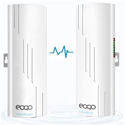
One Master Bridge to multiple Slave BridgesOne bridge works as master mode, the other two or more bridges works as slave mode, all the bridges need to install as face to face, for multiple point connection, the slave bridge direction angle no more than 60 degrees. |
Matching the master and slave bridge channelAdjust the slave bridge channel to match to the master bridge, the both devices will be auto paired in few minutes. |
WPA2-PSK EncryptionThe bridge output WiFi hot point with WPA2-PSK encryption to keep your network in safety, do not worry your privacy to be exposed. |
|
Model: |
CPE335 |
|
Network Interface: |
10/100Mbps 2 * LAN Port |
|
Data Rate: |
11a: 54M, 48M, 36M, 24M, 18M, 12M, 9M, 6Mbps / 11n: 7.2M, 14.4M, 21.7M, 28.9M, 43.3M, 57.8M, 65M, 72.2M, 14.4M, 28.9M, 43.3M, 57.8M, 86.7M, 115.6M, 130M, 144.4Mbps |
|
Power Supply: |
POE 24V 1.0A |
|
Antenna: |
14DBi (5180~5825MHz) |
|
Transmission Range |
3KM / 1.86 miles |
|
Waterproof: |
IP65 |
|
Dust-proof: |
Support |
|
Working temperature: |
-4℉~158℉ |
|
Dimensions: |
250mm * 90mm * 65mm / 9.8'' * 3.55'' * 2.56'' |
|
Weight |
1.1kg / 38.8 oz (A pair) |