Gigabit Wireless Bridge Installation Guide
Model: CPE1100 | CPE1200 | CPE1201 | CPE920
A. Thank you for purchasing our product. Please read the user manual carefully before use. If there are any problems, please contact us in time;
B. The installation of this device requires some network knowledge. If you can't install it, please contact us or ask a professional for help.

Introduce
CPE1200 series bridge is an equipment for long-distance 5.8G wireless point-to-point transmission. It utilizes wireless communication technology. This technology uses the air as a medium to transmit network data to perform point-to-point or point-to-multipoint interconnections over long distances. The working data link layer realizes the interconnection of local area networks. The transmission distance can reach 3 km. The CPE1200 wifi bridge transmission usually consists of two parts: the device is in master mode and slave mode respectively. The bridge connects with the IP camera on the slave side (receiver side), and the bridge connects with the DVR/NVR on the master side (transmitter side). The master bridge can receive wireless data transmission from multiple slave bridges, it is easy and convenient to centrally manage the devices remotely. Point-to-point extension of the network WiFi range, extend the network in the house to your barn, garage, church, warehouse, and even neighbor’s house via wireless bridge
signal transmission. No need to install a new modem and pay monthly, saving you money. Wireless bridges are also widely used in highways, reservoirs and rivers, elevator monitoring systems, field crane monitoring systems, port and wharf monitoring systems, marine aquaculture monitoring systems, etc.
Features:
1. Support Gigabit,1000Mbps RJ45 LAN port;
2. Long distance 5.8Ghz wireless WiFi transmission;
3. Built-in 16dbi high gain WiFi antenna;
4. Transmission distance up to 3km(Barrier-Free);
5. IEEE802.11ac IEEE802.11n, IEEE802.11a, IEEE802.3u;
6. The master bridge output WiFi hotspot, but the slave bridge doesn’t support;
7. Dialing to set the master and slave mode, it is easy to setup;
8. Compatible in both WDS networking mode, video network mode;
9. Support point-to-point, point-to-multipoint mode;
10. Dynamic MIMO power saving mode (DMPS) and APSD;
11. Support 24V POE power supply, easy to install and deploy;
12. Support WEB GUI access to manage the device by PC;
13. 1-year warranty, excellent fast customer technical support.
14. FCC ID certification issued by TCB for compliance with US radio standards;
How we get the wireless bridge working?
The Wireless Bridge has two mode, auto mode and customize mode.
we strang suggest you choose auto mode when you first time use this product, after you get knowledge of the network settings you can switch to customize mode.
Gigabit Wireless Bridge Package

Package Included:
2 x Wireless Bridges
2 x POE Power Adapter
2 x Metal Hoops
1 x User Manual
Note: The wireless bridge is powered by a PoE adapter through a network cable, so it does not require a DC power adapter(Package does not include the DC power adapter). If necessary, you can purchase a 12V 1A DC power adapter by yourself.
Reset Button: Press and hold it over 10 seconds, system will restart, the LED display will flash numeric In setup mode, short press it to change the working channel, it
will display the character from “0”,“1”,“2” ...“A”,“B”... “F” in cycle.
A-B Mode Switch: Move the switch to "A" position, the bridge works as master mode(transmitter), Move the switch to "B" position, the bridge works as slave mode(receiver).

Pairing Guide
1.Preconfigured Bridge
We paired the two bridges before shipment. When you get the bridge, you can use a network cable to connect the PoE adapter and the bridge. Once connected, they will automatically pair and connect. When they are successfully paired, the green signal indicator turns into the solid light states. If you receive the product and they cannot automatically pair and connect, you can read the following instructions to pair and connect.
2.Configure the master and slave mode
There are one pair of wireless bridges in package,simply set one bridge to master mode (switch to “A” position), another bridge to slave mode (switch to “B” position), please refer next diagram:

A. Move the mode switch to “A” position, the device works as master mode, the round light “B-LED” is off.
B. Move the mode switch to “B” position, the device works as slave mode, the round light “B-LED” turns on.
3.Point to Point Pairing Step:
3.1. Switch one bridge to “A” position(Master Bridge) and another bridge to “B” position (Slave Bridge);
3.2. Connect the POE adapter to each bridge via the network cable and plug the POE adapter to power source;
3.3. Wait for the bridges to power on, normally needs about 60 seconds;
3.4. Press the “Reset” button to change the channel. it starts from “0”,“1”,“2”,..., “A”,“B”,“C”,...,“F”,works in cycle;
3.5. Must set both bridges in the same channel, such as channel “1”;
3.6. Wait for 2-5 minutes, both bridges will complete the pairing. When the numeric on the LED digitron is display solid and the signal light on the side of the bridge turns on,
it means the pairing is successful;
3.7. Finally connect the master bridge to the internet source (such as router or DVR) and connect the slave bridge to PC or router or cameras. Install them to the target location. Please refer below diagram:
Connection A: the data transfer through PoE adapter
The Bridge A 1000M port connect to PoE port of the PoE adapter, the LAN port of the PoE adapter connect to 1000M router.
The Bridge B 1000M port connect to PoE port of the PoE adapter, the LAN port of the PoE adapter connect to computer or router.
Please refer the below diagram:

Connection A data transfer path

Connection B: Connect to 1000M port of the bridge
The Bridge A 1000M port connect to the Router, the PoE port of the PoE adapter connect to the 100M port of the bridge A.
The Bridge B 1000M port connect to the computer or router, the PoE port of the PoE adapter connect to the 100M port of the bridge B.
Please refer the below diagram:

Connection B data transfer path

Note:
The “Connection A” must use1000M speed PoE adapter,
The “Connection B” can use 100m or 1000M speed PoE adapter.
We suggest choose the “Connection B”, because the data is transfer from end to end directly, without any delay and it is lossless. It will speed up your bridge A to Bridge B data transfer.
For extend internet access application, the slave bridge can be connect with multiple device, such as Computer or Router, please refer the below diagram:

Note: if the slave bridge connect with router, you will get WiFi hot point output for cell phone, you also can connect it to computer directly.
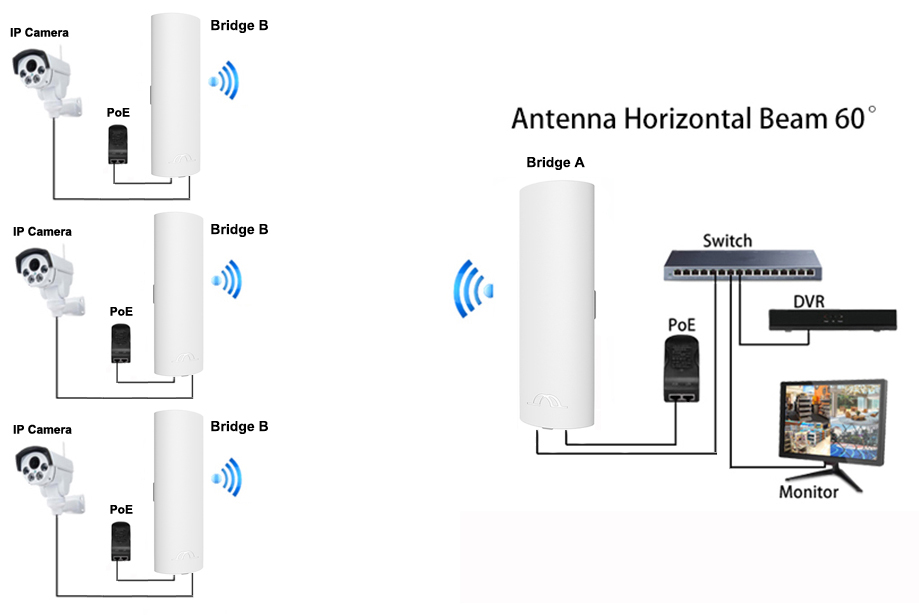
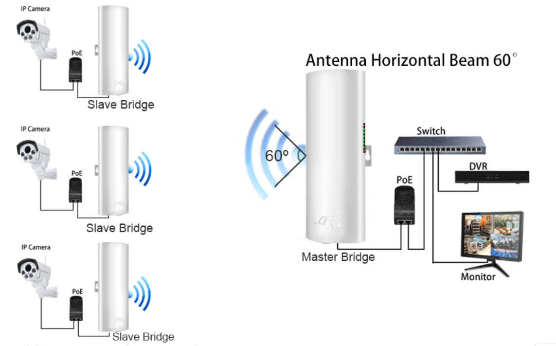
4. Point to Multi-point Pairing Step:
e.g. One master bridge with three slave bridges
4.1. 3.1. Switch one bridge to “A” position(Master Bridge) and three bridges to “B” position (Slave Bridge);
4.2. Connect the POE adapter to each bridge via the network cable and plug the POE adapter to power source;
4.3. Wait for the bridges to power on, normally needs about 120 seconds;
4.4. Press the “Reset” button to change the channel. it starts from “0”,“1”,“2”,..., “A”,“B”,“C”,...,“F”,works in cycle;
4.5. Must set the four bridges in the same channel, such as the channel “C”;
4.6. Wait for 2-5 minutes, both bridges will complete the pairing. When the numeric on the LED digitron is display solid and the signal light on the side of the bridge turns on, it means the pairing is successful;
4.7. Finally connect the master bridge to the internet source (such as router or DVR) and connect the slave bridge to PC or router or cameras. Install them to the
target location. Please refer the bellow diagram:
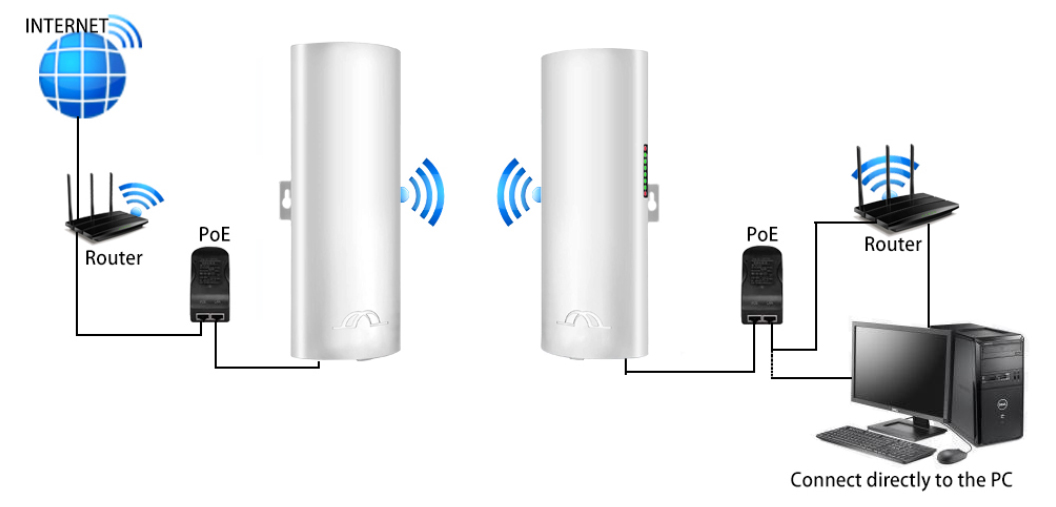
5. Point to Point Internet Extend Connection Example
5.1.Set one bridge to master mode, short press the “Rest” button to adjust the channel to “6", the LED digitron will display “L” for a second, then flash the numeric “6" every second, means the master setting is ok, wait for pairing.
5.2. Set another birdge to slave mode, short press the rest button to adjust the channel to “6", the LED digitron will display “L” for a second, then flash the numeric “6" every second, keep both bridges front side face to face, wait for few seconds, the flash numeric of the LED digitron will stop flash, and change to always light on, please check both bridges are the same status, it means the pairing is successful.
5.3.After the bridges were paired, connect the internet source to the LAN port of the PoE adapter of the master bridge, connect the LAN port of the PoE adapter of the slave bridge to the router or computer’s LAN port, it can extend your WiFi to a long range. The master bridge also provides WiFi hot point (the Slave does not support), you need to enter the password to access, please refer page 10,11,16 to find out the password.
Connect Bridge Via PoE Adapter
Extend your WiFi to a long range topology:

Install Wireless Bridge

1.Put the bridges front side face to face in the same direction, note: the bracket is not included in the package.
2.Use a long network cable to connect the PoE adapter and the bridge. Connect the LAN port of the bridge to the PoE port of the PoE adapter. It's recommended to use a cat 5e(or above) shielded network cable with a ground wire.
3.Connect the LAN port of the PoE adapter to the camera, PC. router or switch. The PoE adapter provides power and data transmission for the bridge.
4. The LAN port of the PoE adapter connects to monitors or the internet for master bridge, and the LAN port of the PoE adapter connects to cameras or routers or other equipment for slave bridge.
Note: before installation, please check whether the wireless bridge is paired well, please refer the master and slave pair setting page.
Installation Tips:
1. The two bridges brackets must be installed face to face and no any block, cannot pass through the walls. and can not be used in strong electricity or strong magnetism environment, please avoid other signal interference between the two wireless bridges, if the transmission is slow or loose connection, you may need to change the bridge's channel to get a free channel.
2. The transmission angle of the bridge is horizontal 60°/ vertical 30°, for point-to-multipoint installation, the slave bridge need to be adjusted to ensure that it is in the signal range of the master bridge.
Advanced Settings
How to Access and Set via Computer
1.Connect the PoE adapter to the wireless bridge via network cable, the bridge gets power from the PoE adapter, it does not need DC power adapter.

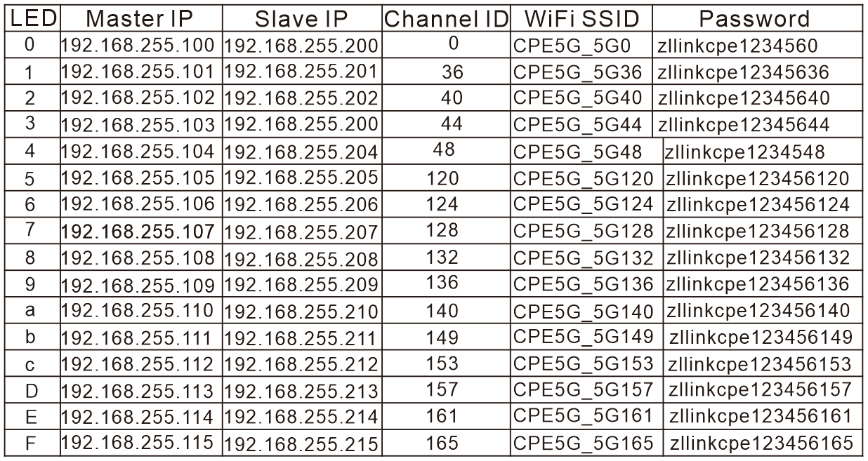
2.Check the numeric on the LED indicator of the wireless bridge, for example: the numeric is 1, and the mode switch of the wireless bridge is at “A” position, then the IP address of the wireless bridge is 192.168.255.101, if the mode switch of the wireless bridge is at “B” position, then the IP address of the wireless bridge is 192.168.255.201, please refer the LED Number match to IP & SSID match to password Chart.

3.LED Number match to IP & SSID match to password Chart, You can find the LED number & IP, SSID & password from this chart.
4.Modify your computer’s IP address to 192.168.255.xxx,(xxx is from 1 -254), please be careful, the computer’s IP address can not be the same with the wireless bridge, and they must be in the same network segment, please Google how to modify computer IP address, it is simple step. Please refer the below diagram:

Step 1: Find and open "Open Network and Sharing Center" on your computer. Tips: click the network icon at the right corner of the bottom of the screen.

Step 2:Select Ethernet and click “Change Adapter Options”.

Step 3: Select "Local Area Connection" to right-click to open the network properties. Refer to the picture above to open.

Step 4: Double-click the “Internet Protocol version 4(TCP/IPv4)” to go to IP config interface

Step 5: Configure your computer IP address as 192.168.255.xxx(xxx is a figure 2-254), note: the Pc’s IP can not be the same with the bridge.

5.Change your computer's IP address to 192.168.255.xxx (192.168.255.xxx cannot be the same with the IP of the CPE), then enter IP address 192.168.255.xxx, the subnet mask is 255.255.255.0(Autofill), the Default gateway is 192.168.255 .xxx, Preferred DDS server 192.168.255.xxx. You can use 192. 168.255.105(xxx=2) in the reference picture to set.
6.After you modified your computer’s IP address, open the browser and enter the IP address of the wireless bridge to access, for example, enter “192.168.255.204" on the browser address column, you can access your bridge control panel.

Note: Please find the IP address of the wireless bridge from the IP correspondence table. If you can't find it, please download the IP scan tool to scan it.
We provide a software for windows system to search the IP address, you can download it on www.eoqo.com/download.html on the download page, select CPE1200 software tool, click to download and unzip it, you can see the software files as below diagram:
Double click the file “find.exe”, it will display below interface:

7.On the login interface, the default user name and login password of the wireless bridge are "admin", just entry the user name and password to login.
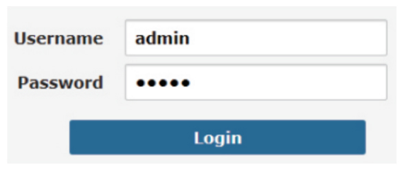
Note: “admin” is not the password of the WiFi SSID, it is just the password for WEB GUI access.
8.Login successful, go to setting.

9.In the wireless settings, turn off "Hide SSID", then modify the SSID name and WiFi password, and finally click "Apply" to complete the setting.

The default name and password is pre-programmed depend on the bridge works channel, it always change the channel when press “Rest” button, so, the name and password is different, but only change the last two or three numeric. For example: the SSID name is CPE5G_5G161, and the default password is zllinkcpe123456161, if the SSID name is CPE5G_5G153, the password should be zllinkcpe123456153, the last three numeric of the password match to the last three numeric of the name.
1.Point to Point Connection:
A. Point to multi-point extended video surveillance diagram, distance: 0.6 ~ 1.86 miles with non-blocking obstacles.

B. Point to multi-point extended network diagram, distance: 0.6 ~ 1.86 miles with non-blocking obstacles.
C. Multiple network equipment expansion diagram,extend the network to your warehouse, barns and garages near your home.

2. Point to Multi-Point Connection:
A. Point to multi-point extended video surveillance diagram, distance: 0.6 ~ 1.86 miles with non-blocking obstacles.

B.Multiples Clients Connection:
Troubleshooting
Trouble 1: Packet Latency
Possible issue:
1. Wireless interference
2. Distance is too long, or there are some walls between the bridges
3. Wireless bridge's install angle in the wrong direction, weak signal
4. The current channel is congested
Solution steps:
1. Use WiFi analysis to choose the best channel,
2. The two wireless bridges should be in 1.86ML distance, avoid the wall
3. Adjust the angle of the bridge according to the signal strength.
4. Update the characters of the bridge and pair again, different characters
represent different channels, a free channel will get better performance.
Trouble 2:Wrong Password
Possible issue:
1. Forget the password
2. Input wrong password
3. WiFi password is confused with the WEB access password
Solution steps:
1. Press the "Rest” button in 10s to reset the bridge, the default password is “admin”.
2. Re-input the password
3.WEB access user name and password is "admin", The WiFi hot-point password you can find on page 10, page 11, page 16.
Trouble 3: Can't access from computer
Possible issue:
1. LAN connection or ethernet cable has issue
2. Local IP is not in the same network segment of the bridge’s IP
3. Local IP is taken by other device
Solution steps:
1. Make sure the wireless bridge is connected to the computer and the
network cable quality is cat 5e or above and it is in good condition.
2. Set the computer's local IPv4 address to the same of the bridge.
For details, please refer to page 11, page 12, page 13.
3. The set IPv4 address is the same as that of other device, so replace it
with other IPv4 addresses.
Trouble 4: System LED light off
Possible issue:
1. PoE adapter is damaged
2. The bridge’s PoE port or LED part may be broken
3. Ethernet cable may loose, RJ45 port may be incorrect, power
current voltage is lower or wrong.
Solution steps:
1. Check wether the PoE adapter or PoE switch works
2. Check wether the PoE port of the bridge is in good condition
3. Check the Ethernet cable connection, may be the network cable
is plugged into the wrong port, please go back to page for details
4. Check wether the voltage is correct, if the socket is broken, and check
the output voltage of the PoE adapter is 24V
5. Contact us for replacement items
Trouble 5: Low transmission Rate
Possible issue:
1. Packet Latency
2. Network cable circuit
3. Network virus attack
4. Too many access users
5. Network cables type lower than Cat 5e
Solution steps:
1. Adjust the distance, angle and channel to decrease latency
2. Check if port is isolated to avoid network virus and broadcast storm
3. Decrease the access users.
4. use a Cat 5e or above network cable.
Trouble 6: Device always dead
Possible issue:
1. Static electricity
2. Running time too long
3. Lightning stroke
Solution steps:
1. Check the bridge or the PoE adapter need a ground connection
2. Running time over 7 days, the system may halt, please reboot it
3. After lightning, the device PoE port may be broken or unstable,
better to deploy the lightning conductor for the bridge.
4. Contact us for replacement items.
Technical Support and Service
Thank you for your purchasing our Wireless Bridge, please read the manual carefully before use.
If there are any problems during the use, please contact us in time.
1. Accessories are missing in the box;
2. If you can't pair or install it;
3. Damaged wireless bridge or PoE power adapter;
4. If the wireless bridge fails or is dead after working for a period of time;
5. No access to the wireless bridge from an computer;
6. The speed provided by the wireless bridge is very slow;
7. For the latest PDF user manual and other questions;
Tech Service email: johnwen0822@gmail.com Skype: johnwen0822