Why my bridge can not get internet?
Why my bridge not getting pair?
Why I can not make the bridge working?
How to find the WiFi password?
How to make the bridge works as access point?
How to extend the bridge to a longer distance with internet access?
Do you have these questions on the wireless bridge which your purchase? please read the following guide to understand how to set it.
Set the wireless bridge to auto mode do not need any network technology, please following the below step to make your bridge works in few minutes.
Step1: Unpack the wireless bridges, open the back cover of the bridge, please refer the below diagram:
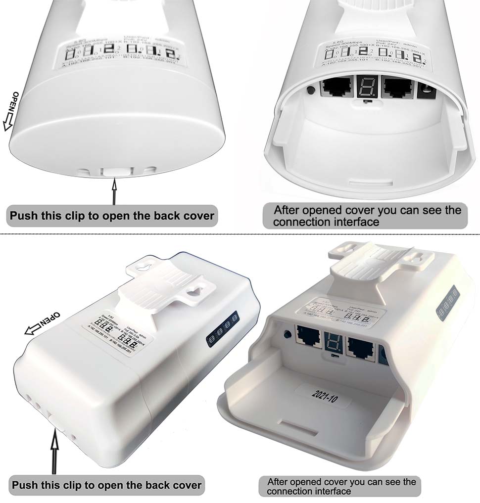
All the model CPE 335 | CPE 355 | CPE 365 | CPE450 | CPE220 | CPE 550 | CPE320 back cover is similar design, you can open the back cover by this step.
Step2: Move the mode switch to "A" position to set one bridge to master mode, and move another bridge's mode switch to "B" position to set to slave mode, please refer the below diagram:
CPE520 | CPE550 | CPE560 | CPE570 | CPE650 | CPE750 Interface:

CPE220 | CPE320 | CPE350 Interface:

All the model CPE335 | CPE355 | CPE365 | CPE450 | CPE220 | CPE550 | CPE320 are same interface, move the mode switch to "A" position to set to set the device works as master mode, move the mode switch to "B" position to set to set the device works as slave mode, you must set one bridge to master mode, and another to slave mode.
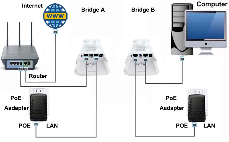
Step3.1: Internet Access Extend Method 1: Connect the two bridges to POE power adapter, and the master bridge connect to internet, the slave bridge connect to computer, please refer the below diagram:
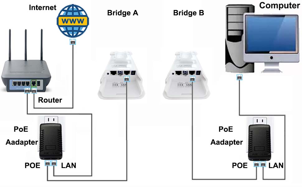

A: Master Bridge: The bridge A must set to master mode(the mode switch should be at "A" position), connect the "LAN" port of the bridge A to "POE" port of the PoE adapter via network cable, connect the LAN port of the PoE adapter to "LAN" port of the router by network cable, and connect your router to internet source.
B: Slave Bridge: The bridge B must set to slave mode(the mode switch should be at "B" position), connect the "LAN" port of the bridge B to "POE" port of the PoE adapter via network cable, connect the LAN port of the PoE adapter to "LAN" port of the computer by network cable.
Now, the connection is completed, please refer the network transmission path as bellow diagram:
CPE220 | CPE320 | CPE350 Transmission Path 1:
CPE520 | CPE550 | CPE560 | CPE570 | CPE650 | CPE750 Transmission Path 1:
Note:
a. Please be careful the PoE adapter "POE" and "LAN" port connection, the "POE" port must connect to bridge, this port is output electronic power to power the bridge & data transmission, the "LAN" port is output or input data and transmission to "POE" port. you must install to the correct port, otherwise, the device may do not have internet.
b. The bridge has "LAN1" "LAN2" port, you can choose one port for connection and left another empty, the DC 5V port of the bridge do not need connect to power supply, because the PoE adapter powered to the bridge via network cable, so, just left it empty.
c. For the model CPE220 | CPE320 | CPE335 | CPE355 | CPE365 | CPE450 | CPE550 Please check the router LAN port should be 100Mbps standard, these model only supports 100Mbps transmission speed.
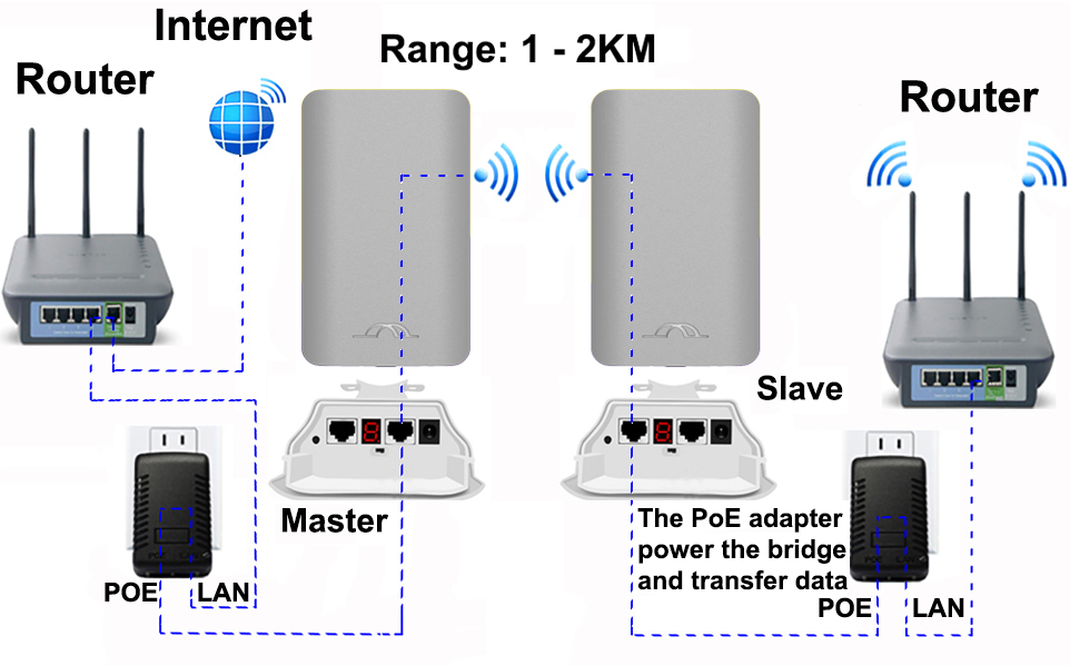
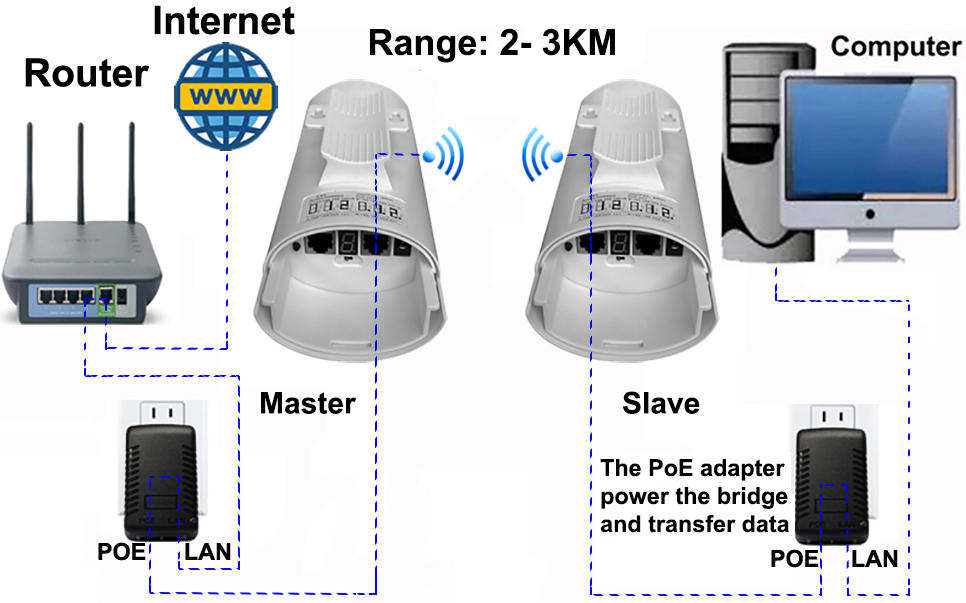
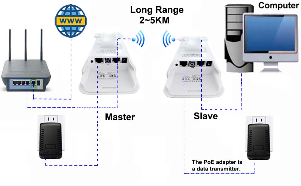
Step3.2: Internet Access Extend Method 2: Connect the two bridges to POE power adapter, the PoE power adapter only power on the device, and the master bridge connect to internet directly, the slave bridge connect to computer directly, please refer the below diagram:
A: Master Bridge: The bridge A must set to master mode(the mode switch should be at "A" position), connect the "LAN" port of the bridge A to "LAN" port of the router by network cable, and connect your router to internet source.
B: Slave Bridge: The bridge B must set to slave mode(the mode switch should be at "B" position), connect the "LAN" port of the bridge B to "LAN" port of the computer by network cable.
Now, the connection is completed, please refer the network transmission path as bellow diagram:
CPE220 | CPE320 | CPE350 Transmission Path 2:
CPE520 | CPE550 | CPE560 | CPE570 | CPE650 | CPE750 Transmission Path 2:
Note:
a. The bridge has "LAN1" "LAN2" port, you can choose one port for power supply and another for data transfer, you also can power the bridge by the DC 5V port, in this way you can connect it to your solar power system, or solar panel, please make sure the voltage is 5V input and the current must over 150mah.
c. For the model CPE220 | CPE320 | CPE335 | CPE355 | CPE365 | CPE450 | CPE550 Please check the router LAN port should be 100Mbps standard, these model only supports 100Mbps transmission speed.
After the installation completed, the status LED light of the both bridges are turn on and the both bridges will auto pairing in one minutes, please refer the below diagram:
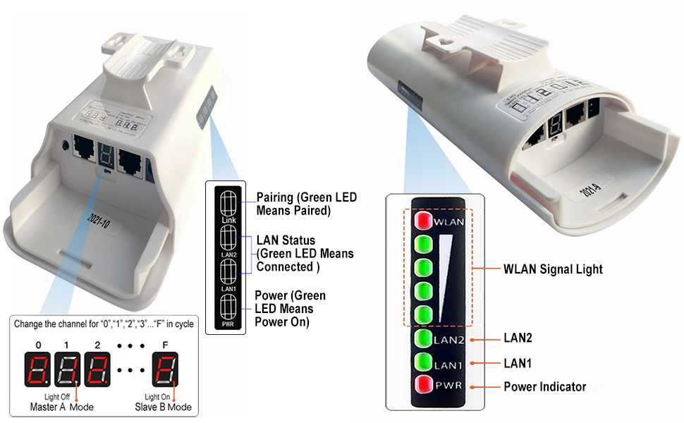
The bridge status LED light and it means:
For the model CPE335 | CPE355 | CPE365 | CPE450 | CPE550
1. Power Indicator: When the bridge power on, the power indicator LED light turn on, and the LED light of the PoE adapter turn on.
2. LAN1 LAN2: When the bridge data connection is successful, the green LED light will turn on, otherwise it will be off.
3. WLAN: The red light turn on indicates the bridges are paired successful, 4 grid green signal light indicates the signal strength.
For the model CPE220 | CPE320
1. Power: When the bridge power on, the green LED light turn on
2. LAN1 LAN2: When the bridge data connection is successful, the green LED light will turn on
3. Link: The green light turn on indicates the bridges are paired successful
The Digital display numeric and it means:
When the bridge is power on, the both bridge's display will flashing a numeric for 30 ~ 60 seconds, when the both bridges are paired successful, the display will first flashing the numeric "L" for 2 seconds, then the digital display solid display a numeric, and the mean time the status LED light LAN1 or LAN2 turn on, means the both device are paired successfully.
Most of customers ask the questions:
Q: Why my wireless bridge can not get internet?
A: Please check the PoE adapter connection port is correct, and check the router LAN port is correct, if above steps are ok, please change another LAN port of the bridge, please also make sure the two bridges are installed face to face, because the bridge antenna has direction, if you installed with different direction, it will not get paired.
Q: My bridge digital display shows "O", what issue?
A: In this situation please press the "RST" over 10 seconds and release, let the bridge go back to factory mode and will pair again later.
How to change the bridge working channel?
Some time the 5.8ghz channel may have interference and your bridge may disconnection or lost data, you can change to another channel, a numeric is means a channel, short press the "RST" button to change the numeric for "0","1","2"..."A","B","C"..."F" in cycle. please change the both bridges in the same numeric, and wait for another 30 ~ 60 seconds let the bridges get auto pairing. when it paired successful, the digital display will always display the changed numeric.
How to find the WiFi password?
The name and password is pre-programed, it has different name and password when the bridge works at different channel, but only change the last two or three numeric.
Fox example: the WiFi SSID name is "CPE5G_5G161", and the default password is "zllinkcpe123456161", if the SSID name is "CPE5G_5G153", and the password should be "zllinkcpe123456153", the last three numbers of the password is match to the last three numeric of the SSID name.
Note: The channel "A","B","C","D","E","F" does not output WiFi hot point, for wifi hot point access, you have to set the bridge's channel to "0","1","2"..."9".
Please refer the LED Indicator Number & SSID password Chart, to find your bridge SSID name and the password
LED Indicator Number & SSID password Chart:
| LED Indicator Display Value | Channel ID | WiFi SSID | Password |
| 0 | 0 | CPE5G_5G0 | zllinkcpe1234560 |
| 1 | 165 | CPE5G_5G165 | zllinkcpe123456165 |
| 2 | 161 | CPE5G_5G161 | zllinkcpe123456161 |
| 3 | 157 | CPE5G_5G157 | zllinkcpe123456157 |
| 4 | 153 | CPE5G_5G153 | zllinkcpe123456153 |
| 5 | 149 | CPE5G_5G149 | zllinkcpe123456149 |
| 6 | 48 | CPE5G_5G48 | zllinkcpe12345648 |
| 7 | 44 | CPE5G_5G44 | zllinkcpe12345644 |
| 8 | 40 | CPE5G_5G40 | zllinkcpe12345640 |
| 9 | 36 | CPE5G_5G36 | zllinkcpe12345636 |
| a | 140 | ||
| b | 132 | ||
| c | 124 | ||
| d | 116 | ||
| e | 108 | ||
| f | 100 |
How to make the bridges works as Access Point?
When the both bridges get paired successful, the master bridge will output the WiFi hot point, it could be transfer to 2 ~ 3km away(no block) in a 60 degree, the slave bridge also can connect a router to share the WiFi in another building (the router can transmit over 2, 3 walls), please refer the below diagram:

Install the both bridges front side face to face, the master connect to router and internet source, the slave connect to the router to forwarder the WiFi signals to computer and cellphones, and other device. you need set the slave router WiFi SSID name and password.

the master bridge also output a WiFi hot point, it support transmission up to 3KM with a 60 degree of the front side of the bridge. you just need enter the password to get access. Please refer the How to find the WiFi password? section and LED Indicator Number & SSID password Chart to find the password.
Step 3.2: Extend video surveillance, it support extend video surveillance distance: 0.6 ~ 1.9 miles /1KM - 3KM with non-blocking obstacles, please refer the below diagram:

The above step is all for the auto mode settings, we strong suggest the newbie to use this mode for your installation, it is simple and easy plug to play method to extend your internet access or video surveillance.
The shortcut page is for pair the wireless bridge quickly, for the more details please visit Customize Mode Shortcut Guide or Wireless Bridge User Manual
For any more questions please contact us by email johnwen0822@gmail.com or skype: johnwen0822