Wireless Bridge Installation Guide

Model: CPE220 | CPE320 | CPE450 | CPE520 | CPE550 | CPE560 | CPE570 | CPE820
A. Thank you for purchasing our product. Please read the user manual carefully before use. If there are any problems, please contact us in time;
B. The installation of this device requires some network knowledge. If you can't install it, please contact us or ask a professional for help.
How we get the wireless bridge working?
The Wireless Bridge has two mode, auto mode and customize mode.
1. Auto mode: simply connect the bridges with POE adapter and internet source, one set for "A" mode, another set to "B" mode, the both bridges will pair automatically, no any other settings, just plug to play.
In this mode, you can use the bridge to extend network access(point to point method) or works as long range video surveillance transmission(point to point method), please visit Auto Mode Shortcut Guide for more details.
2. Customize mode: by this mode you need connect to computer to configure the parameters, you must familiar with network technology, otherwise it may lose internet or not working properly.
In this mode, you need enough network knowledge, it can works with point to multiple point for video surveillance or network extend, please visit Customize Mode Shortcut Guide for more details.
we strang suggest you choose auto mode when you first time use this product, after you get knowledge of the network settings you can switch to customize mode.
1. Wireless Bridge Overview
CPE335 CPE355 CPE385 CPE450 Interface:

CPE220 CPE320 Interface:

Note: The operation of the 5 models is the same, we choose CPE220 as the default image.
Package Included:
2 x Wireless Bridges
2 x POE Power Adapter
2 x Metal Hoops
1 x User Manual

2. Install Wireless Bridge

1. Put the bridges front side face to face in the same direction, note: the bracket is not included in the package.
2. Use a long network cable to connect the PoE adapter and the bridge.
Connect the LAN port of the bridge to the PoE port of the PoE adapter. It's recommended to use a cat 5e(or above) shielded network cable with a ground wire.
3. Connect the LAN port of the PoE adapter to the camera, PC. router or switch. The PoE adapter provides power and data transmission for the bridge.
4. The LAN port of the PoE adapter connects to monitors or the internet for master bridge, and the LAN port of the PoE adapter connects to cameras or routers or other equipment for slave bridge.
Note: before installation, please check whether the wireless bridge is paired well, please refer the master and slave pair setting page.
3. Pre-Paired Wireless Bridges, Plug & Play
The two bridges are pre-paired in factory. When you get the bridges, you can use an Ethernet cable to connect the PoE adapter and the bridge. Once connected, they will pair and connecting automatically. When they are successfully connected, the green signal indicator turns into the solid light state. If you receive the product and they cannot automatically pair and connect, you also can read the following instructions to pair and connect by yourself.
4. Video Transmission & Network Extend
The wireless bridge is widely used in highways, reservoir river monitoring, elevator monitoring systems, site crane monitoring systems, port terminal monitoring systems, marine aquaculture monitoring systems and so on.
The wireless bridge for video transmission usually covers in master and slave mode respectively. At the slave side(transmitting data) the bridge connects with the IP camera. At the master side(receiving data)the bridge connects with a video recorder. The master receives wireless data transmitted from multiple clients, and it's easy and convenient for centralized management of the remote equipment.
The wireless bridge not only helps you in remote monitoring, but also helps you extend the network signal to warehouses, barns, garages and other buildings near your home.
5. Wireless Bridge Function
1.Long-distance 5.8G wireless transmission
2.Support point-to-point, point-to-multipoint mode
4.Campatible in both WDS networking mode and video networking mode
5.Dialing to set the transmitter and receiver, and also support the PC to modify the IP settings.
6.Dynamic MIMO power saving mode (DMPS) and automatic power saving transmission(APST)
7.Pre-configued wireless bridge, digital displays A, B automatic networking, plug and play.
8.Support 24V POE power supply, convenient installation and deployment, simply construction, safe and reliable.
9.The wireless bridge can be relocated and reused, installation is fast, flexible and cost effective.
6. Wireless Bridge Parameters
Model: CPE220 / CPE320 / CPE335 / CPE355 / CPE385 / CPE450
Master Control: Ar9344
DRAM: DDR2 64MByte
FLASH: 8Mbyte
Wire Interface: 10/100Mbps LAN*2
CPE Transmission Rate: 300Mbps
Transfer Method: Direct Sequence Spread Spectrum(DSSS)
Modulation: OFDM/BPSK/QPSK/CCK/DQPSK/DBPSK
Network Standard: IEEE802.11n, IEEE802.11a,IEEE802.3u
Supporting Agreement: CSMA/CA,TCP/IP,IPX/SPX,NetBEUI,DHCP,NDIS3,NDIS4,NDIS5
Frequency Range: 4900-6100MHz
Power Consumption: 3W
Power Scheme: PoE 24V 0.5A-1A
Antenna Gain: 12DBi/14DBi
Antenna Polarization Direction: Vertical (Horizontal 60°C / Vertical 30°C )
Management Settings: WEP management, Telnet, Serial
Encryption: WEP encryption 64/128bits, WPA, WPA2,802.1x
Operating Temperature: -30°C ~ 65°C
7. Connect Wireless Bridge to PoE Adapter
7.1 Master bridge with POE adapter and Switch connection

7.2 Slave bridge with POE adapter and camera connection

8. Wireless Bridge Master & Slave Pairing
8.1 Configure the master and slave mode
There are one pair wireless bridges in the package, simply set a bridge to master mode (switch to “A” position), another bridge to slave mode (switch to “B” position), please refer below diagram:

a. move the mode switch to “A” position, the device works as master mode, the round LED light on.
b. move the mode switch to “B” position, the device works as slave mode, the round LED light turn on.
How to pair it?
Set a bridge to master mode, another to slave mode, short press the reset button to change the channel from "0" - "F", the LED indicator will display the numeric to show what channel it is, please keep the master and slave both in the same channel.

Note: the bridges are pre-paired, just connect to PoE adapter, it will auto pair in a few minutes, you can adjust the channel.
Reset: if the system halt, press and hold the "RST" button over 10 seconds, system will restart, the LED display will flash numeric
8.2 Example
1. move the switch to master mode, short press the rest button to adjust the channel to “6", the LED indicator will display “L”for a second, then flashes the numeric “6" every second, means the master setting is ok, wait for pairing.
2. move the switch to slave mode, short press the rest button to adjust the channel to “6", the LED indicator will display “L” for a second, then flashes the numeric “6" every second, keep both bridges front side face to face, wait for a few seconds, the flashes numeric of the LED indicator will stop flashing, and change to always light on, please check the master bridge should be the same status, now, the pair is successful.

After the bridges were paired, connect the internet source to the LAN port of the PoE adapter of the master bridge,the LAN port of the PoE adapter of the slave bridge connect to router or computer’s LAN port, it can be extend your WiFi to a long range.

The master bridge also provide WiFi hot point(the Slave does not support), you need enter the password to access, please referLED Number match to IP & SSID match to password Chart to find out the password.
Product Overview

8.3 LED Indication & Function Chart:
| WLAN | WLAN solid red light on indicates pair successful,4 grid green signal light indicates the signal strength |
| LAN1/LAN2 | When the bridge data connection is successful, the LED light will turn on, otherwise it will be off. |
| PWR | Power indicator, when the bridge connected to power source, the LED light turn on. |
| Led Digitron |
LED Digitron display "H" indicates in manual configuration status; LED Digitron display"L"and flashing indicates in setting status; Digitron flash indicates setting the config or connecting, solid light on indicates that the pair is successful. The digital LED indicator displays "O" and flashing means the "DIP switch control" on the bridge control panel(UI) is disabled. |
| A-B Switch | The switch to change the bridge works as master or slave mode, at “A” position represents the master bridge mode, “B” represents the slave. |
| PoE/LAN | PoE adapter LAN PoE Port,24V power supply and 300Mbps data transmission. |
| LAN | Only data transfer, 10/100/1000Mbps RJ45 port. |
| Point Light | When the light is turn on the device works on "B" mode, when the light is off, the device is on "A" mode. |
| RST | Short press the RST button to change the channel from 0,1,2,3...F in cycle. |
| RST | Press and hold the RST button over 10 seconds, release it, the system will restart. |
9.How to Access and Set via Computer
9.1 connect to the computer for configuration
9.11.Connect the PoE adapter to the wireless bridge via network cable, the bridge gets power from the PoE adapter, does not need DC power adapter.
9.12. Connection A: the POE port of the power adapter to the LAN port of the bridge
Connection B: the LAN port of the power adapter to the LAN port of the computer

9.13. Check the numeric on the LED indicator of the wireless bridge, for example: the numeric is 1, and the mode switch of the wireless bridge is at “A” position, then the IP address of the wireless bridge is 192.168.255.101, if the mode switch of the wireless bridge is at “B” position, then the IP address of the wireless bridge is 192.168.255.201, please refer the 9.13.1 LED Number match to IP & SSID match to password Chart.

9.13.1 LED Number match to IP & SSID match to password Chart:
| LED Indicator Display Value | (A)Master Mode IP | (B)Slave Mode IP | Channel ID | WiFi SSID | Password |
| 0 | 192.168.255.100 | 192.168.255.200 | 0 | CPE5G_5G0 | zllinkcpe1234560 |
| 1 | 192.168.255.101 | 192.168.255.201 | 165 | CPE5G_5G165 | zllinkcpe123456165 |
| 2 | 192.168.255.102 | 192.168.255.202 | 161 | CPE5G_5G161 | zllinkcpe123456161 |
| 3 | 192.168.255.103 | 192.168.255.203 | 157 | CPE5G_5G157 | zllinkcpe123456157 |
| 4 | 192.168.255.104 | 192.168.255.204 | 153 | CPE5G_5G153 | zllinkcpe123456153 |
| 5 | 192.168.255.105 | 192.168.255.205 | 149 | CPE5G_5G149 | zllinkcpe123456149 |
| 6 | 192.168.255.106 | 192.168.255.206 | 48 | CPE5G_5G48 | zllinkcpe12345648 |
| 7 | 192.168.255.107 | 192.168.255.207 | 44 | CPE5G_5G44 | zllinkcpe12345644 |
| 8 | 192.168.255.108 | 192.168.255.208 | 40 | CPE5G_5G40 | zllinkcpe12345640 |
| 9 | 192.168.255.109 | 192.168.255.209 | 36 | CPE5G_5G36 | zllinkcpe12345636 |
| a | 192.168.255.110 | 192.168.255.210 | 140 | ||
| b | 192.168.255.111 | 192.168.255.211 | 132 | ||
| c | 192.168.255.112 | 192.168.255.212 | 124 | ||
| d | 192.168.255.113 | 192.168.255.213 | 116 | ||
| e | 192.168.255.114 | 192.168.255.214 | 108 | ||
| f | 192.168.255.115 | 192.168.255.215 | 100 |
9.13.2. Modify your computer’s IP address to 192.168.255.xxx,(xxx is from 1 -254), please be careful, the computer’s IP address can not be the same as the wireless bridge, and they must be in the same network segment, please google how to modify computer IP address, it is simple step.
9.14 How to configure your PC IP address: 192.168.255.xxx:
a. Find the network icon at the bottom right corner of the screen, click it to open the Network & Internet settings.

b. Select Ethernet and click “Change Adapter Options”.

c. Find the network connection you are using, right click it and select “Properties”

d. Double-click the “Internet Protocol version 4(TCP/IPv4)” go to IP config interface:

e. Configure your computer IP address as 192.168.255.xxx(xxx is a figure 2-254), note: the Pc’s IP can not be the same as the bridge.

9.15 We provide a software for window system to search the IP address, you can download it on www.eoqo.com/download.html
on the download page, select CPE software tool, click to download and unzip it, you can see the software icon as below diagram:

Double click this sofware, it will display below interface:

1. Click the down arrow, please refer arrow "1"
2. Click the scan button, please refer arrow "2"
System will start searching the connected wireless bridge, after a few seconds you can see the IP address on the IP address column.
9.16 Log into master bridge and slave bridge control panel
9.16.1. After you modified your computer’s IP address, open the browser and enter the IP address of the wireless bridge to access, for example, enter “192.168.255.204" on the browser address column, you can access your bridge control panel.

The browser login interface as below diagram:

Note: If enter the ip address, the screen does not display the login interface, please check the network cable connection, and make sure your computer's IP address must be 192.168.255.xxx.
Enter the Username and Password, the default user name and password is "admin / admin"
select language to “English”, click “Login” to confirm and go to the below interface:

On "Quick Setup" menu, you can modify the user password, click "Apply" button to confirm
The master bridge output WiFi hot point at auto mode, we need to enter the password to access it, how do we find the password? please refer the following content to get it.
When the "DIP Switch Control" is enabled, the bridge has pre-programed the WiFi hot point name(SSID) and password, you can click "Setting" of the left menu, and click "wireless" you can view and change the password if needed:
The name and password is pre-programed, it has different name and password when the bridge works at different channel, but only change the last two or three numbers.
Fox example: the WiFi SSID name is "CPE5G_5G161", and the default password is "zllinkcpe123456161", if the name is "CPE5G_5G153", and the password should be "zllinkcpe123456153", the last three numeric of the password is match to the last three numeric of the SSID name.
9.2 Bridge Setting

On the bridge setting menu, you can set the bridge parameters
DIP Switch Control: check it to enable auto mode, press the "RST" button is functional, for the operation details please refer page 8, uncheck it to disable it, the "RST" button is not functional, the bridge works in customization mode, you can set the bridge parameters for customized function.
Note: if you unchecked the "DIP Switch Control", the device is works at customization mode, it will not auto pairing and "RST" button not functional, please be careful, it may lose the connection of your bridges after your configured.
If you are not familiar with network technology, please checked the "DIP Switch Control", system works at auto mode, and do not make any changes.
Mode: you can select A(master) and B(Slave) mode
Matching ID: you can select bridge working frequencies, please refer the 9.13.1 chart to find out the number matching to 5.8G frequencies, for example: "40(5200MHZ)", 40 is match as below diagram:
| LED Indicator Display Value | (A)Master Mode IP | (B)Slave Mode IP | Channel ID | WiFi SSID | Password |
| 8 | 192.168.255.108 | 192.168.255.208 | 132 | CPE5G_5G132 | zllinkcpe123456132 |
The channel is 8, for (A)master mode the IP address is 192.168.255.108, for (B)slave mode the IP address is 192.168.255.208
Fixed IP address: here you can change the bridge's IP address, it must be in this format 192.168.255.xxx, after changed, click "OK" button to save the settings.
Host Name: you can set the bridge with a special name for remember.
9.3 Access Point Setting

DHCP: check to enable, uncheck to disable, this function must enable, otherwise it can not assign the IP address to bridge
Fixed IP Address: set a customize IP address, should be in this IP segment: 192.168.255.xxx
Fixed Netmask: set the netmask address
DNS server: set the DNS server if needed
Click "Next" to go to Wireless setting interface:

phy0 channel: set the working frequencies, same as Matching ID
Wireless: check to enable wireless, uncheck to close wireless function
Name(SSID): here you can enter your own SSID name
Authorization: you can select "Open" or "WPA2-PSK"
Wireless Bridge(WDS): check to enable wireless bridge function, uncheck to close the function, we suggest to enable it
Click "Next" to go to Management setting interface

Mac Layer Management Service: check to enable, uncheck to disable, we suggest to enable
Click "OK" button to confirm and save the settings.
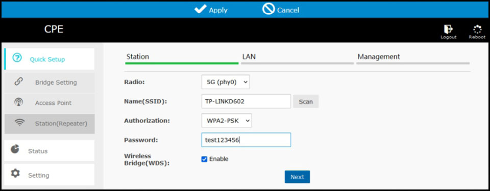
9.4 Station(Repeater) Setting

This interface can set your device works as wireless access point repeater, support repeat LAN or WiFi source
Radio: 5G(phy0), only support 5G
Name(SSID): click "Scan" button to searching the WiFi source, it will pop a window for you choose, refer the WiFi source selection chart on next page
Authorization: it will auto change after your scanned WiFi source
Wireless Bridge(WDS): check to enable, uncheck to disable, if use for repeater mode, you need to disable this function, for wireless bridge connection usage you need enable it.
WiFi source select chart

On this pop window, you can select your router name and click > to setect the WiFi router, here we choose "TP-LINKD602"
Please enter your router WiFi password in the password column

CLick "Next" button to go to "LAN" setting interface
Note: if you use as repeater mode, must disable "Wireless Bridge(WDS)" function, otherwise it will not working.

Wireless Repeater: check to enable, uncheck to disable, for repeater mode, you need enable it
Name(SSID): Enter the WiFi hot point name
Authorization: you can select "Open", or "WPA2-PSK", if you choose "WPA2-PSK", you also need to set the password.
DHCP: check to enable, uncheck to disable, must enable
Fixed IP Address: set an customize IP address
Fixed Netmask: set the netmask address
DNS Server: set the DNS server if needed
Check "Next" button to go to Management setting interface:

Mac Layer Management Service: check to enable, uncheck to disable, we suggest to enable
Click "OK" button to confirm and save the settings.
Click "Setting" of the left menu, and click "Wireless", it will display below interface, you can check the parameters again

TP-LINKD602 is the WiFi router source, home-cpe353 is the bridge's WiFi hot point, for AP repeater access please disable the wireless bridge(WDS), must enable the home-cpe353, click "Apply" button at the top of the screen to confirm.
Now you can use your cell phone or laptop to connect the WiFi hot point for internet surfaces.
Click "Status" of the left menu, system will display the following interface:

For customization setting is a little bit hard for newbie, if you can not set or system halts, please press and hold the bridge's "RST" button over 10 seconds, when the LED display flashes numeric then release it, system will return to factory mode.
The factory mode is enough for most of usage, it will auto pair and easy to change the channel without computer access, the master bridge also output WiFi hot point, you just need to find the password and enter it to get access.
The customization mode could be used for point to multiple points for networks access and video surveillance, once it is connected, you can use the computer to access each bridges by different IP address, your computer's IP should be same segment to the bridges, the format is 192.168.255.xxx, when connected to your WiFi router source, the IP will change to this format: 192.168.0.xxx, you need to take care, if there is no response, please reset it.
10. Application
10.1 Point to Point Connection:
A. point to point long range video surveillance diagram:
Distance: 0.6 ~ 1.9 miles /1KM - 3KM with non-blocking obstacles

B. point to point long range network extend diagram:
Distance: 0.6 ~ 1.9 miles /1KM - 3KM with non-blocking obstacles
C. Multiple network equipment long range access diagram:
Distance: 0.6 ~ 1.9 miles /1KM - 3KM with non-blocking obstacles

Extend the network to your warehouse, barns and garages near your home
10.2 Point to Multi-Point Connection:
Point to multi-point long range video surveillance diagram:
Distance: 0.6 ~ 1.9 miles /1KM - 3KM with non-blocking obstacles

10.3 Multiples Clients Connection:
Distance: 0.6 ~ 1.9 miles /1KM - 3KM with non-blocking obstacles

11. Tips
1. The installation of this device requires network knowledge, if you can’t install it, please contact us or ask a professional for help, if the product you receive is damaged or miss any accessories, please contact us for exchange or repair.
2. The wireless transmission maximum speed(wireless bridge A to B unit) is 300Mbps, the LAN network transmission maximum speed(POE adapter to wireless bridge connection) is 100Mbps, the LAN port is 100Mbps standard.
Troubleshooting
Trouble 1: Packet Latency
Possible issue:
1. Wireless interference
2. Distance is too long, or there are some walls between the bridges
3. Wireless bridge's install angle in the wrong direction, weak signal
4. The current channel is congested
Solution steps:
1. Use WiFi analysis to choose the best channel,
2. The two wireless bridge should be in 1.86ML distance, avoid the wall
3. Adjust the angle of the bridge according to the signal strength.
4. Update the characters of bridge and pair again, different characters represent different channel, a free channel will get better performance.
Trouble 2:Wrong Password
Possible issue:
1. Forget the password
2. Input wrong password
3. WiFi password is confused with the WEB access password
Solution steps:
1. Press the "Rest” button in 10s to reset the bridge, the default password is “admin”.
2. Re-input the password
3.WEB access user namer and password is "admin", The WiFi hotpoint password you can find on LED Number match to IP & SSID match to password Chart.
Trouble 3: Can't access from computer
Possible issue:
1. LAN connection or ethernet cable has issue
2. Local IP is not in the same network segment of the bridge’s IP
3. Local IP is taken by other device
Solution steps:
1. Make sure the wireless bridge is connected to the computer and the network cable quality is cat 5e or above and it is in good condition.
2. Set the computer's local IPv4 address to the same of the bridge. For details, please refer to the page 11, page 12, page 13.
3. The set IPv4 address is the same as that of other device, so replace it with other IPv4 addresses.
Trouble 4:System LED light off
Possible issue:
1. PoE adapter is damaged
2. The bridge’s PoE port or LED part may broken
3. Ethernet cable may loose, RJ45 port may incorrect, power current
voltage is lower or wrong.
Solution steps:
1. Check the PoE adapter or PoE switch is works
2. Check the PoE port of bridge is good condition
3. Check the Ethernet cable connection, may the Ethernet cable plugged into wrong port, please go back to page for details
4. Check the voltage is correct, if the socket broken, and check the output voltage of the PoE adapter is 24V
5. Contact us for replacement items
Trouble 5:Low transmission Rate
Possible issue:
1. Packet Latency
2. Network cable circuit
3. Network virus attack
4. Too much access users
5. Network cables type lower than Cat 5e?
Solution steps:
1. Adjust the distance, angle and channel to decrease latency
2. Check if port isolated to avoid network virus and broadcast storm
3. Decrease the access users.
4. Change use an Cat 5e or above network cable.
Trouble 6:Device always dead
Possible issue:
1. Static electricity
2. Running time too long
3. Lightning stroke
Solution steps:
1. Check the bridge or the PoE adapter need a ground connection
2. Running time over 7 days, the system may halt, please reboot it
3. After lightning, the device PoE port may broken or unstable,
better to deploy the lightning conductor for the bridge.
4. Contact us for replacement items.
Technical Support and Service
Thank you for your purchasing our Wireless Bridge, please read the manual carefully before use.
If there are any problems during the use, please contact us in time.
1. Accessories are missing in the box;
2. If you can't pair or install it;
3. Damaged wireless bridge or PoE power adapter;
4. If the wireless bridge fails or is dead after working for a period of time;
5. No access to the wireless bridge from an computer;
6. The speed provided by the wireless bridge is very slow;
7. For the latest PDF user manual and other questions;
Tech Service email: johnwen0822@gmail.com Skype: johnwen0822